


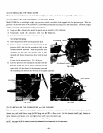
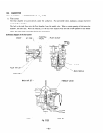
3) Align the mounting holes at the lateral side of the front cover with those in the bracket which are bolted to the fuel
tank. Then. install the fuel tank. using t\vo $16 x Emm flange bolts.
4) hlake sure that the flexible shait on the control dial side is inserted in the square hole of the strainer shaft. then fasten
the flexible shait .
124-30 INSTALLING THE REAR COVER
Align the mounting holes at the lateral side of the rear co\-er urth those in the
fuel
tank bracket. Then install the rear cover-.
using two 516 x gmm Slang2 bolts.
Also align the holes at the lolver part of the rear cover s-ith those in the base plate. and
install the rear co\-er by two M6 x Smm flange bolts.
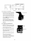
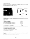
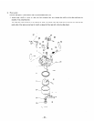
124-31 INSTALLING THE FUEL TANK HANDLE
1) Set the bolt (to secure the tank handle) in the handle and assemble the O-ring to this bolt from the opposite side.
Then. tighten the bolt to install the handle to the
fuel
tank.
NOTE:
Be sure to direct the less slanted part of the handle toward the front cover.
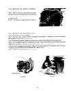
2) Insert the rubber tube end over the protrusion oi the bolt (for the
15121
tank)
and push it
down to the base of the pro-
trusion.
NOTE:
Be sure to keep the air bleed hole at the center of the rubber tube directed upward.
3) Place the handle cover over the handle.
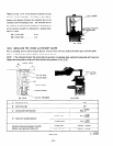
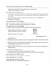
12-4-32 INSTALLING THE FUEL LINE
Insert the fuel line end over the fuel strainer joint (be sure to push the line end down to the joint base). and secure it with
the clamp.
12-4-33 INSTALLING THE CHOKE CABLE
1 j Insert the choke cable adjusting screw in its hole on the fuel tank bracket.
2) Secure this adjusting screw with the M6 nut and tighten to the midway point of the threaded part.
3) Set the dial of the control panel to STOP. and connect the locknut of the choke cable end to the panel.
4) Pull the inner wire of the choke cable to clamp the wire to the choke lever. using the setscrew.
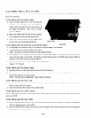
124-34 CONNECTING THE COUPLERS TOGETHER
Connect the coupler (6Pj from the generator to the coupler (6P) extending from the control panel.
Also connect the stop wire (green) as required.
12-435 INSTALLING THE LEFT and RIGHT SIDE COVERS
Using the MS flange screlvs. install the left and right side covers in place.
-47-