l
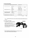
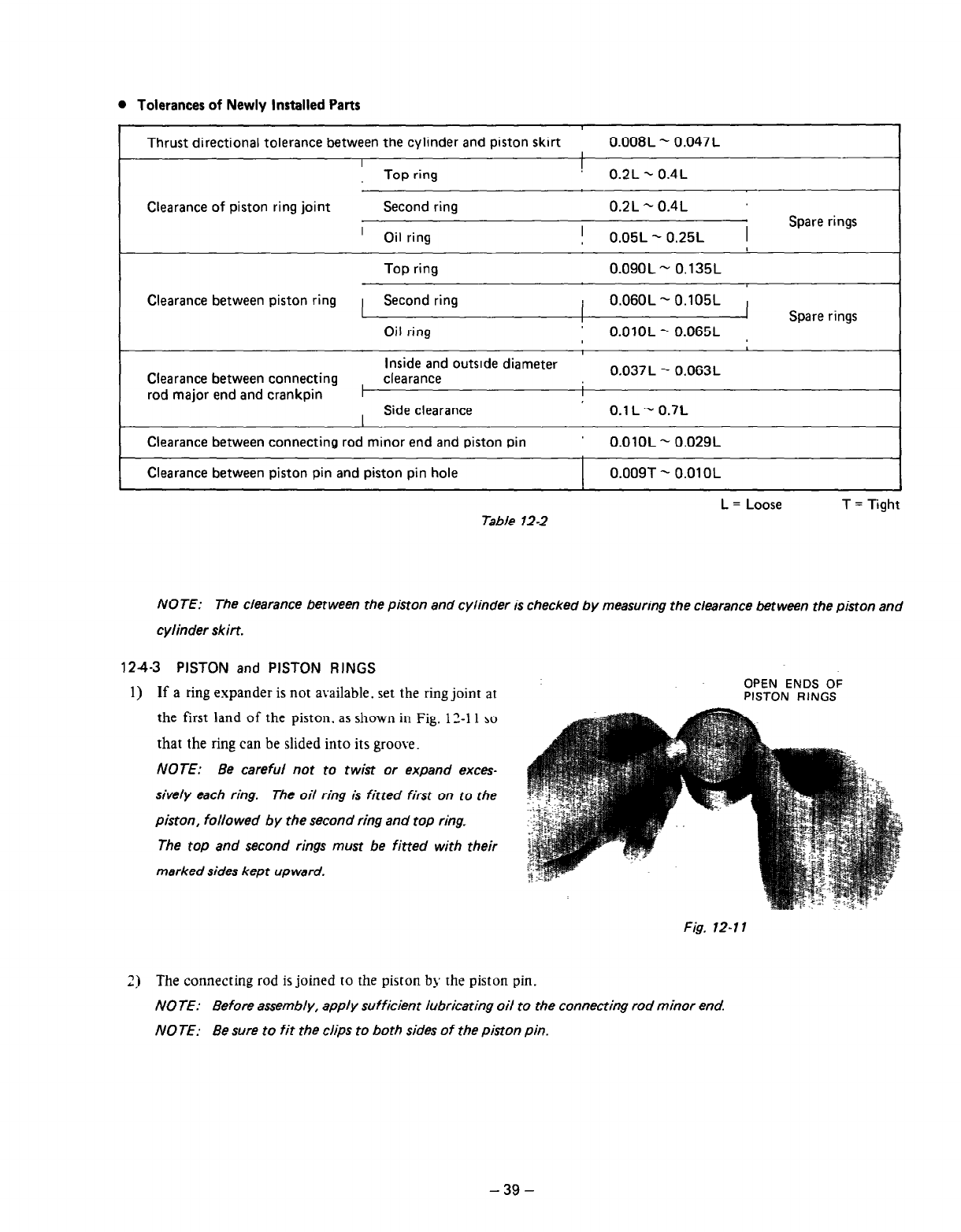
Tolerances of Newly Installed Parts
Thrust directional tolerance between the cylinder and piston skirt
0.008L - 0.047L
I
I
Top ring
! 0.2L - 0.4L
Clearance of piston ring joint
Second ring 0.2L - 0.4L
’ Oil ring
! 0.05L - 0.25L 1
Spare rings
Top ring
0.09OL - 0.135L
Clearance between piston ring Second ring 1 0.06OL - 0.105L
I
Spare rings
Oil ring
O.OlOL-0.065L ,
Inside and
outslde diameter
Clearance between connecting clearance
0.037 L - 0.063L
rod major end and crankpin
I
Side clearance 0.1 L - 0.7L
Clearance between connecting rod minor end and piston pin
O.OlOL - 0.029L
Clearance between piston pin and piston pin hole
0.009T - 0.01 OL
L = Loose T = Tight
Table 12-2
NOTE: The clearance between the piston and cylinder is checked by measuring the clearance between the piston and
cylinder skirt.
124-3 PISTON and PISTON RINGS
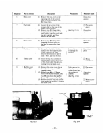
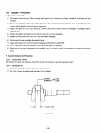
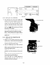
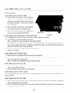
1) If a ring expander is not available. set the ring joint at
OPEN ENDS OF
PISTON RINGS
the first land of the piston. as shown in Fig. 12-l 1 so
that the ring can be slided into its groove.
NOTE: Be careful not to twist or expand exces-
sively each ring. The oil ring is fitted first on to the
piston, followed by the second ring and top ring-
The
top
and second rings must be fitted with their
marked sides kept upward.
Fig. 12-l 1
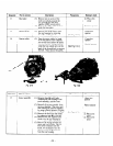
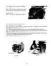
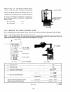
~j The connecting rod is joined to the piston by the piston pin.
NOTE: Before assembly, apply sufficient lubricating oil to the connecting rod minor end
NO JE: Be sure to fit the clips to both sides of the piston pin.
-39-


