


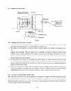
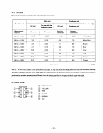

10-2 MEASURING AC OUTPUT
SWlTFf; LOAj
TOACd+)@ km77
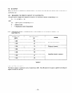
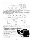
With the circuit shown in Fig.lO-7.measurement 1s made of the AC output of the generator. An electric heater or an in-
candescent lamp with a power factor of 1 .O is suitable as a load for the generator.
When the measured AC output of the generator is confirmed to be wnhin the voltage range specified in the table belon.
over its voltage rating. the AC output is normal.
Measurement must
be
made under rated load and at rated speed; sometimes. load and speed adjustments are necessary-.
Voltage
I
rating
11ou
12ou
220u
230,240U
Range of
voltage
108% 12OU
118- 130U 218 - 240U
235 - 260U
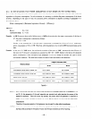
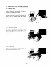
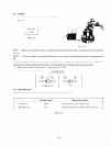
10-3 MEASURING DC OUTPUT
Table 10-l
SWITCH
DC TERMINAL
Fig. 10-8
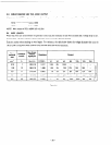
Measurement is made of the DC output of the generator with the witch shown in the abobe circuit turned on while the
generator is kept running at its rated speed. The DC output should be aithin 1 1 to 14V. Lvith the current regulated
at
8.3A
by adjusting the load connected to the generator.
NOTE: If a battery is connected as a load to the generator, the DC output voltage will increase by approximately 1 to 2V.
Therefore, carefully observe the electrolyte level and do not to overcharge the battery.
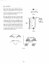
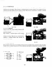
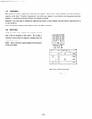
IO-4 MEASURING INSULATION RESISTANCE
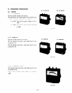
To measure insulation resistance. connect the megger tester
across either one of the two output terminals of the socket
and the earth terminal. When the measured insulation
resistance of the generator is over lMI2. it is normal (over
1OMR at time of shipment).
(Be sure to turn on the circuit breaker when measuring
insulation resistance.)
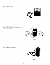
If the insulation resistance is less than 1X19. drsassemble
the generator. and measure the respective resistances of the
stator.
rotor and control panel.
Fig. 10-9
- 23 -