


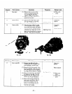
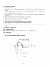
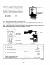
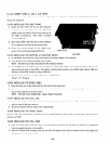

*Shown in Fig. 12-18. is the method to measure the side
clearance of the crankshaft. According to this method,
measure the clearance between the machined face of the
crankcase and the adjusting collar. The machined face of
the crankcase is mounted with packing so it is necessary to
set the clearance properly by allowing for a packing thick-
ness of O.??mm. -I
M6 x 25mm bolt . . . . . . . . . 8 PCS.
M6 x 55mm bolt . . . . . . . . . 1 pc.
Fig. 72-78
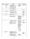
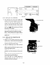
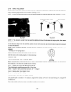
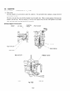
12-4-8 INSTALLING THE INTAKE and EXHAUST VALVES
Prior to installing. remove carbon and gum deposits, from the valve, valve seat, intake and exhaust ports, and valve guide.
NOTE: If the valve face is worn, replace the valve with a new one.
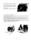
NOTE: If the clearance between the valve guide and valve stem is excessively large, replace the valve guide with a new one.
Replace the valve guide by using a pull block and pull bolt as shown in Fig.
72-20.
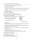
A
VALVE FACE
VALVE SEAT
- VALVE STEM
VALVE GUIDE
VALVE SPRING
E GUIDE
PULLER
Fig. 72-79
‘VALVE RETAINER
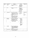
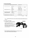
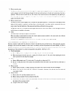
A:
Valve
face angle
B: Valve seat angle
C: Valve guide inside diameter
D: Valve stem outside diameter
Intake valve
Exhaust valve
Fig. 72-20
45”
45O
I
5 59 +0.018
I
0
I
-0.020
I
5’59 -0.032
I
-0.056
5.5@ -0.074
Clearance (clearance between C and D)
between valve guide and valve stem
Intake valve
0.02OL - 0.05OL
Exhaust valve
0.056L - 0.072L
Table 72-3
L: LOOSE
-42-