


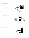
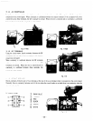
11-1-4 AC RECEPTACLES
Using the circuit tester. check continuity between the t\vo terminals at the rear of the XC receptacles while the receptacle is
mounted on the control panel. When continuity is confirmed between the output terminals of the receptacle Lvvlth a \vtre
connected across these terminals. the AC receptacle is normal. When the wire is removed and no continuity- is eonfirmed
between these terminals. the receptacles are also normal.
Fig. 7 7-4(A)
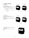
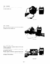
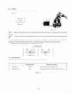
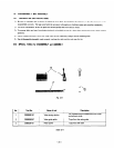
11-1-5 DC TERMINALS
Csmg the circuit tester. check continuity between the DC
terminals at the rear side of the control panel while they are
mounted on the panel.
Ben continuity- is confirmed bet\veen the DC terminals
Lvith a wire connected across these terminals. the DC
terminals are normal. When the wire is removed and no
continuity is <onfirmed between these terminals. the
terminals are also normal.
Fig. 1 l-4(81
Fig. 1 l-5
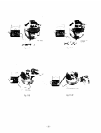
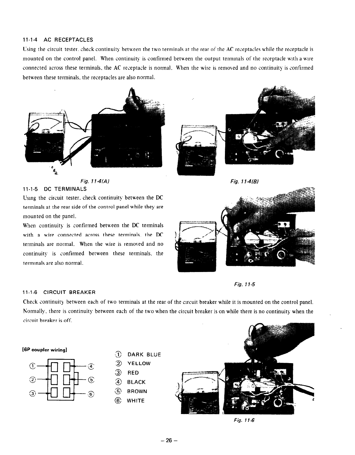
11-1-6 CIRCUIT BREAKER
Check continuity between each of two terminals at the rear of the circuit breaker while it is mounted on the control panel.
Normally. there is continuity between each of the two lvhen the circuit breaker is on while there is no continuiq when the
circuit breaker is
ofi.
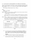
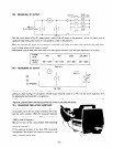
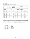
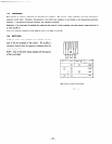
16P coupler wiring]
DARK BLUE
YELLOW
RED
BLACK
BROWN
WHITE
Fig. 11-6
- 26 -