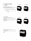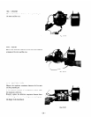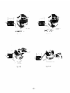
10-4-1 STATOR
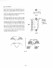
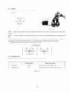
Measure the resistances
the stator and the core.
betlveen red coupler leading from
Fig. lo-10
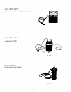
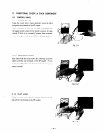
1 O-4-2 ROTOR
d
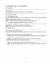
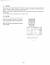
Measure the insulation resistance across one of the soldered
terminals of the rotor and the core.
Fig. 10-11
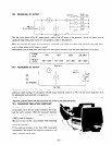
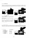
10-4-3 CONTROL PANEL
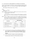
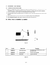
Measure the insulation resistances between the live parts
and the grounded part.
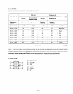
If the measured resistance of a component is below 1MR.
the insulation is defective.
Promptly replace the defective component because there
may be leakage of current from the generator and a poten-
_
tial danger of electrical shock.
Fig. 10-12
- 24 -


