


PAGE 34 — SG1400C3 STUDIO GENERATOR • OPERATION AND PARTS MANUAL — REV. #1 (02/15/12)
STARTUP
BEFORE STARTING
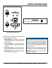
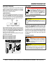
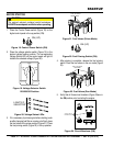
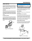
1. Place the Control Power switch (Figure 18) on the
digital control panel in the up position (ON).
Figure 18. Control Power Switch (ON)
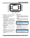
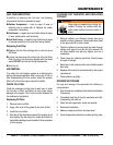
2. Place the voltage selector switch (Figure 19) in the
desired voltage setting position. The corresponding
Voltage Status LED on the control panel will light to
indicate the selected voltage (Figure 20).
Figure 19. Voltage Selector Switch
120/208 3Ø Position
Figure 20. Voltage Status LEDs
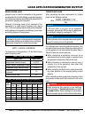
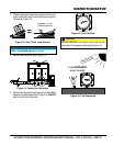
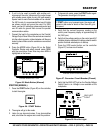
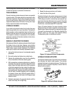
3. If it is necessary to prime engine before starting (such
as after changing fuel filter or running out of fuel), place
the fuel valves in the prime position (Figure 21). Place
the fuel priming switch (Figure 22) in the up position.
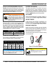
CAUTION
The engine’s exhaust contains harmful emissions.
ALWAYS have adequate ventilation when operating.
ON (UP)
120/208
277/480 120/240
3
1
3
LIGHTS IF
SELECTED
Figure 21. Fuel Valves (Prime Mode)
Figure 22. Fuel Priming Switch (ON)
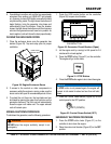
4. After priming is complete, release the fuel priming
switch. Place the fuel valves in the run mode (Figure
23).
Figure 23. Fuel Valves (Run Mode)
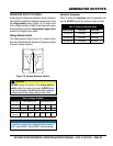
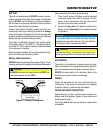
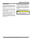
5. Verify that all three circuit breakers (Figure 24)are in
the ON position prior to starting the engine.
Figure 24. Circuit Breakers (ON)
FUEL VALVES IN
PRIME MODE
ON (UP)
FUEL VALVES IN
RUN MODE
Electronic Trip Unit
Instantaneous Trip Setting - Amps
Push to Trip
Test
Status
A — 500
B — 600
C — 800
D — 1000
E — 1250
F — 1500
G — 2000
H — 2500
E
D
C
B
A
H
G
F
450 AMP
LONG — INST.
ON
VERIFY CIRCUIT
BREAKERS ARE ON