


SG1400C3 STUDIO GENERATOR • OPERATION AND PARTS MANUAL — REV. #1 (02/15/12) — PAGE 25
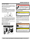
CAMLOK/VOLTAGE OUTPUT PANEL
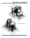
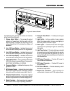
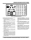
The definitions below describe the controls and functions
of the Camlok/Voltage Output Panel (Figure 7).
1. CB4/CB5 Circuit Breakers — These circuit breakers
protect the 120 VAC auxiliary output receptacles from
overload.
2. CB6/CB7 Circuit Breakers — These circuit breakers
protect the bates output receptacles from overload.
3. Generator Voltage Test Points — To determine if
the generator's output voltage is present and correct,
connect a test meter to these test points during
troubleshooting and maintenance.
4. Paralleling Cable In — This Ethernet input connection
point is used when multiple generators are going to be
connected.
5. Paralleling Cable Out — This Ethernet output
connection point is used when multiple generators are
going to be connected.
6. BUS Hot Indicator Lamp — When lit, this indicator
lamp informs that the voltage bus is active (high
voltage). NEVER connect or disconnect cables from
the camlok or auxiliary receptacles when this indicator
is ON. The possibility exists of electrocution, shock or
even death if cables are connected or unplugged when
this indicator is lamp lit.
7. 120 VAC Output Receptacles — These 15-amp
receptacles provide 120 VAC output. The maximum
allowable combined amps (both receptacles) is 25 amps
when the voltage selector switch in the 3Ø 277/480 VAC
position.
8. Bates 120VAC Output Receptacles — These
receptacles provide AC voltage output. Each receptacle
is protect by a 100 amp breaker. These receptacles
cannot be used when the voltage selector switch is in
the 3Ø 277/480 VAC position.
9. Camlok Receptacles — These output voltage
connection points (6 pairs) are used for load connection.
ALWAYS pay close attention when connecting and
disconnecting power cables from these camlok
receptacles. The possibility exists of electrocution,
shock or even death if cables are connected or
unplugged when the bus hot indicator lamp is lit.
3
4
5
6
7 7
88
GREEN WHITE RED BLUE BLACK
9
1 2
Figure 7. Camlok/Voltage Output Panel