


PAGE 24 — SG1400C3 STUDIO GENERATOR • OPERATION AND PARTS MANUAL — REV. #1 (02/15/12)
CONTROL PANEL
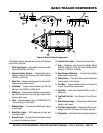
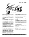
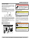
The definitions below describe the controls and functions
of the Control Panel (Figure 6).
1. Voltage Adjust Switch — To increase the output
voltage, pull upward and hold the switch until the
desired voltage is achieved by monitoring the AC
voltage display (item 8). To decrease the voltage, pull
downward.
2. Line 1 AC Amps Display — Indicates the amount of
current the load is drawing from line 1 of the generator.
3. Line 2 AC Amps Display — Indicates the amount of
current the load is drawing from line 2 of the generator.
4. Line 3 AC Amps Display — Indicates the amount of
current the load is drawing from line 3 of the generator.
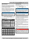
5. Voltage Status LEDs — During operation these status
LED's will indicate the phase/voltage of the generator,
3Ø-277/480, 3Ø-120/208 or 1Ø-120/240.
6. Frequency Display — Indicates the frequency of the
generator in Hertz.
7. AC Voltmeter Display — Indicates the output voltage
present at the camlok terminals. This display is used in
conjunction with the voltmeter select switch (item 8).
8. Voltmeter Selector Switch — Place switch in desired
position to read line-line or line-neutral voltage. Switch
is used in conjunction with AC voltmeter display (item 7).
9. Digital Controller — Starts and stops the generator
and monitors various engine operating parameters.
10. Controller Power Switch — Provides power to engine
controller.
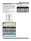
11. Light Switch — In the up position, turns on exterior
lights. In the down position, turns on panel lighting. In
the center position, turns off all lights.
12. Panel Lights — Located on each side of the digital
control panel is a panel light. Lights are activated by
light switch.
13. Light Timer Control — The interior lights are controlled
by an electronic turn dial timer that allows the operator
to turn on the lights inside the generator for up to 15
minutes. The lights will automatically shut off when the
timer reaches zero.
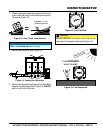
14. AC Output Connector — Provides AC power to
various electronic assemblies.
15. DC Output Connector — Provides DC power to
engine interface.
16. Fan Control Module — Provides necessary control
electronics to operate fan.
17. Engine Com Connector — 9-pin connector for
communication to engine via a PC with engine software.
1
8
7
6
2
3
4
5
17
9
10
11
12
13
14
15
16
Figure 6. Control Panel