


46
Section 5: Maintenance & Lubrication
RCB6610 & RCBM6610 Series 2 S/N 944730+ Rotary Cutters 330-584M
11/11/12
Table of Contents
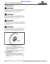
Type B Clutches
Clutch Run-In
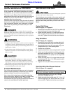
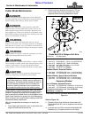
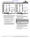
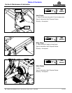
Refer to Figure 5-13:
1. Using a pencil or other marker, scribe a line across the
exposed edges of the clutch plates and friction disks.
2. Carefully loosen each of the 6 nuts by exactly 1
revolution. It will be necessary to hold hex end of
retainer bolt in order to count the exact number of
revolutions.
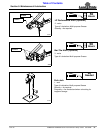
3. Make sure the area is clear of all bystanders and
machine is safe to operate.
Type B Clutch Run-In
Figure 5-13
4. Start tractor and engage PTO drive at idle for 2-3
seconds to permit slippage of friction plates.
Disengage PTO, shut off tractor, and remove key.
Wait for all components to come to a complete stop
before dismounting from tractor.
5. Inspect clutch to ensure that the scribed markings
made on the clutch plates and friction disc have
changed positions. If any two marks are still aligned,
then the clutch did not slip as it should. Skip to
step 8 if all clutch plates slipped.
6. If the friction clutch did not slip, loosen the nuts one
more revolution. Make sure the nuts have full thread
engagement on the bolt and then repeat steps 4 - 5.
7. A clutch that does not slip must be disassembled to
separate the friction disk plates. See “Clutch
Disassembly, Inspection & Assembly” below.
8. Tighten each of the nuts on the clutch back to their
original location to restore clutch pressure.
9. Allow clutch to cool to ambient temperature before
operating again. Clutch is now ready for use.
10. The clutch should be checked during the first hour of
cutting and periodically each week. An additional set
of scribe marks can be added to check for slippage.
Clutch Disassembly, Inspection & Assembly
The clutch must be disassembled into its separate friction
disks if clutch run-in procedure indicated that one or more
friction disks did not slip. See disassembly instructions.
Disassembly
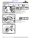
26618
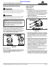
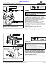
IMPORTANT: Do not remove nuts (#8) from
bolts (#7) until after Belleville spring (#6) is relaxed
and not pressing against any of the six nuts (#8).
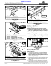
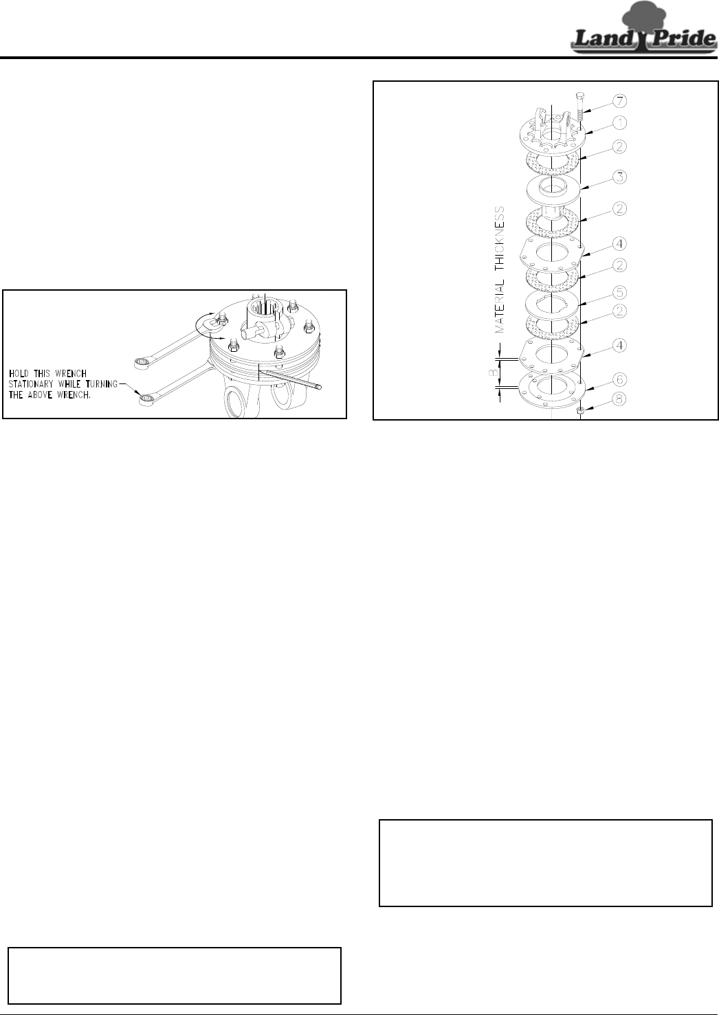
Type B 4 Plate Clutch Assembly
Figure 5-14
Refer to Figure 5-14:
1. Unscrew nuts (#8) equal amounts until all belleville
spring tension is removed. Do not remove nuts until
tension against all nuts has been removed.
2. Remove nuts (#8) and bolts (#7).
3. Separate all friction disks (#2) from plates (#4 & #5),
hub (#3) and yoke flange (#1).
Inspection
Inspect all parts for excessive wear and condition. Clean
all parts that do not require replacement.The original
friction disk thickness is 1/8" (3.2mm) and should be
replaced if thickness falls below 3/64" (1.1mm). If
clutches have been slipped to the point of “smoking”, the
friction disks may be damaged and should be replaced.
Heat build-up may also affect the yoke joints.
Assembly
1. Reassemble each friction disk (#2) next to the metal
plate it was separated from.
2. Install bolts (#7) through end plates and intermediate
plates as shown and secure with nuts (#8).
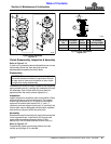
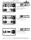
3. Tighten belleville spring (#6) until spring is tight
against drive plate (#4) & then back nuts (#8) up
3 and 1/6 revolutions, “B” = 5.5 mm (0.217”).
If a higher torque is needed, then tighten nuts
another 1/6 of a revolution, Do not set gap “B” smaller
than 5 mm (0.197").
26638
IMPORTANT: Measurement “B” is an approximate
distance. Variations in spring force and friction
materials may cause some differences in torque
values. Tightening nuts (#8) one revolution will
compress 4-plate clutch 1.75mm (.069").