


12
Section 1: Assembly & Set-up
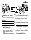
RCB6610 & RCBM6610 Series 2 S/N 944730+ Rotary Cutters 330-584M
11/11/12
Table of Contents
Section 1: Assembly & Set-up
If your tractor is not equipped with two duplex outlets, an
optional control valve kit is available from your local Land
Pride dealer. See “Selector Control Valve Kit” on page
39 for information about the hydraulic kit.
Before You Start
Read and understand the operator’s manual for your
cutter. An understanding of how it works will aid in the
assembly and setup of your cutter.
It is best to go through the Assembly Checklist before
assembling the cutter. Speed up your assembly task and
make the job safer by having all needed parts and
equipment readily at hand.
Torque Requirements
See “Torque Values Chart” page 62 to determine
correct torque values when tightening hardware. See
“Additional Torque Values” at bottom of chart for
exceptions to common torque values.
Assembly Checklist
Check Reference
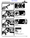
Have a fork lift or loader with properly sized chains and
safety stands capable of lifting and supporting the
equipment on hand.
Have a minimum of two people available during
assembly.
Make sure all major components and
loose parts are shipped with the machine.
Operator’s
Manual
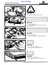
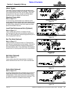
Double check to make sure all parts,
fasteners, and pins are installed in the
correct location. Refer to the Parts
Manual if unsure. By double checking,
you will lessen the chance of using a bolt
incorrectly that may be needed later.
NOTE: All assembled hardware from the
factory has been installed in the correct
location. Remember location of a part or
fastener if removed during assembly.
Keep parts separated.
Operator’s
Manual
330-584M
Parts
Manual
334-071P
Make sure working parts move freely,
bolts are tight & cotter pins are spread.
Operator’s
Manual
Make sure all grease fittings are in place
and lubricated.
Page 49
Make sure all safety labels are correctly
located and legible. Replace if damaged.
Page 4
Make sure all red and amber reflectors
are correctly located and visible when
machine is in transport position.
Page 10
Make sure all tires are inflated to the
specified psi air pressure and all wheel
bolts and axle nuts are tightened to the
specified torque.
Page 62
Tractor Requirements
Horsepower
!
WARNING
Do not use too small a tractor. Tractors that are too small can
be pushed around and/or flipped over by the weight of the
cutter. Tractors that are too large can damage the cutter.
Tractor horsepower should be within the range noted
below. Tractors outside the range must not be used.
Horsepower Rating . . . . . . . . . . . . . . . . . .50-250 HP
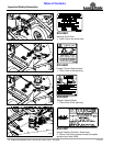
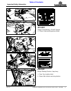
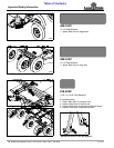
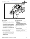
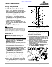
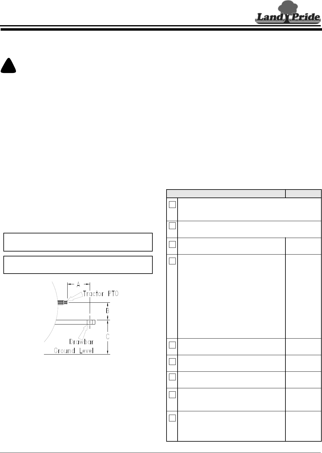
Drawbar Set-up
Refer to Figure 1-1:
Maintain proper distance, dimension A, between center
of drawbar hitch pin hole and end of tractor PTO shaft.
Hitch Type . . . . . . . . . . . . . . . . . . . . . . . . . . Draw Bar
540 RPM & 1 3/8", 1000 RPM Rear PTO Speed:
A . . . . . . . . . . . . . . . . . . . . . . . . . . . . . . . . . 14"- 16"
B . . . . . . . . . . . . . . . . . . . . . . . . . . . . . . . . . 8" - 10"
C. . . . . . . . . . . . . . . . . . . . . . . . . . . . . . . . 18" - 22"
1 3/4", 1000 RPM Rear PTO Speed:
A . . . . . . . . . . . . . . . . . . . . . . . . . . . . . . . . 18" - 20"
B . . . . . . . . . . . . . . . . . . . . . . . . . . . . . . . . .10" - 12"
C. . . . . . . . . . . . . . . . . . . . . . . . . . . . . . . . 18" - 22"
PTO to Drawbar Distance
Figure 1-1
PTO Speed
Rear PTO Speed:
Model RCB6610 . . . . . . . . . . . . . . . . . . . . 540 RPM
Model RCBM6610. . . . . . . . . . . . . . . . . . 1000 RPM
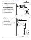
Hydraulic Outlets
Two duplex outlets are required. One to raise and lower
the cutter, and one to fold the wing. Float position is
highly recommended for the wing.
IMPORTANT: PTO damage may occur if distances
“A” and “B” are not properly maintained.
IMPORTANT: A PTO adaptor should not be used.
Using a PTO adaptor can damage the PTO.
22273