


25
Section 1: Assembly & Set-up
11/11/12
RCB6610 & RCBM6610 Series 2 S/N 944730+ Rotary Cutters 330-584M
Table of Contents
Unhook Rotary Cutter
1. S e e “Long Term Storage” on page 48 if parking the
cutter for long periods and end of season.
2. Disengage PTO, park on a level hard surface. Place
tractor gear selector in park or set park brake.
3. Raise center deck fully up.
4. Wait for blades to come to a complete stop and then
fold wing up to transport position.
5. Shut tractor engine off and remove switch key before
dismounting from tractor.
Refer to Figure 1-25:
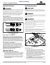
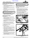
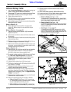
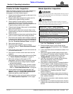
6. Place transport lock pin (#2) in transport lock
holes (B). Make sure pin is secured with hairpin
cotter (#3).
Refer to Figure 1-21 on page 23:
7. Remove stroke control spacers (#4) from center
hydraulic cylinder.
8. Start tractor and lower cutter until front skids are on
the ground.
9. Shut tractor engine off and remove switch key before
dismounting tractor.
10. Replace stroke control spacers (#4) on lift cylinder as
needed to support wheels at this height.
11. Return to the tractor seat. With no one around or near
the cutter, move cylinder lift levers back and forth to
release hydraulic line pressure.
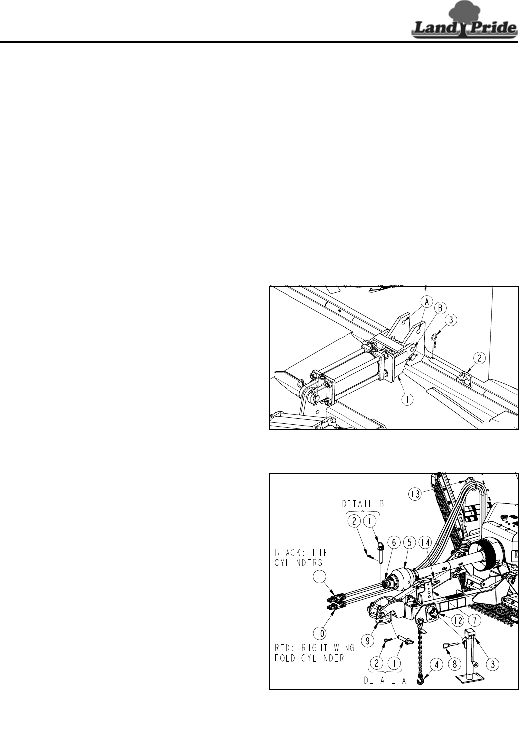
Refer to Figure 1-26:
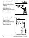
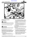
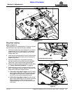
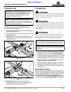
12. Remove park jack (#3) from weight box and attach to
jack mount (#12) as shown. Fully insert detent
pin (#8) in jack mount to secure park jack.
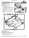
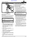
13. If needed, realign park jack (#3) to be vertical. Refer
to “Park Jack Angle Alignment” on page 26.
14. Unhook hydraulic hoses (#10 & #11) from tractor
duplex outlets. Store coupling ends in hose
holder (#14).
15. Unhook hitch safety chain (#4) from tractor.
16. Pull back on locking collar (#6) and pull driveline (#5)
from tractor PTO shaft.
17. Collapse driveline (#5) by pushing tractor end of
driveline toward the splitter gearbox.
18. Rotate driveline hanger (#7) up to position shown
and store driveline on hanger. If height of driveline
hanger needs readjusting, refer to “Adjust Driveline
Hanger” on page 21.
19. Adjust park jack (#3) to raise cutter up until all load is
removed from tractor drawbar.
20. Remove connecting hitch pin or bolt as follows:
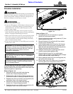
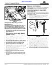
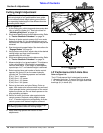
a. Refer to Detail A in Figure 1-26: If unhooking
LP Performance hitch or standard clevis, remove
hairpin cotter (#2) and hitch pin (#1).
b. Refer to Figure 1-11 on page 17: If unhooking
bar-tite hitch, remove lock nut (#2) and bolt (#1).
21. Restart tractor and drive tractor slowly forward
several feet.
22. Shut tractor down properly before dismounting.
23. Lower park jack (#3) until skid shoes support cutter.
24. Replace connecting pin/bolt (#1) as follows:
a. Refer to Detail A in Figure 1-26:
If unhooking LP Performance hitch, insert hitch
pin (#1) in horizontal hitch holes to support clevis
level. Secure with hairpin cotter (#2)
b. Refer to Detail B in Figure 1-26:
If unhooking standard clevis, replace connecting
pin (#1) in clevis hitch pin holes and secure with
hair pin cotter (#2).
c. See Figure 1-11 on page 17:
If unhooking bar-tite hitch, remove hitch (#10)
from tractor and attach it to cutter hitch (#9) with
bolt (#1) and lock nut (#2) Screw lock nut on 4 or
5 full turns. Do not torque nut tight.
Wing Transport Lock
Figure 1-25
Unhook Rotary Cutter (LP Performance Hitch Shown)
Figure 1-26
30173
37986