


36
Section 4: Options & Accessories
RCB6610 & RCBM6610 Series 2 S/N 944730+ Rotary Cutters 330-584M
11/11/12
Table of Contents
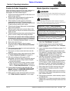
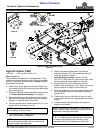
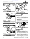
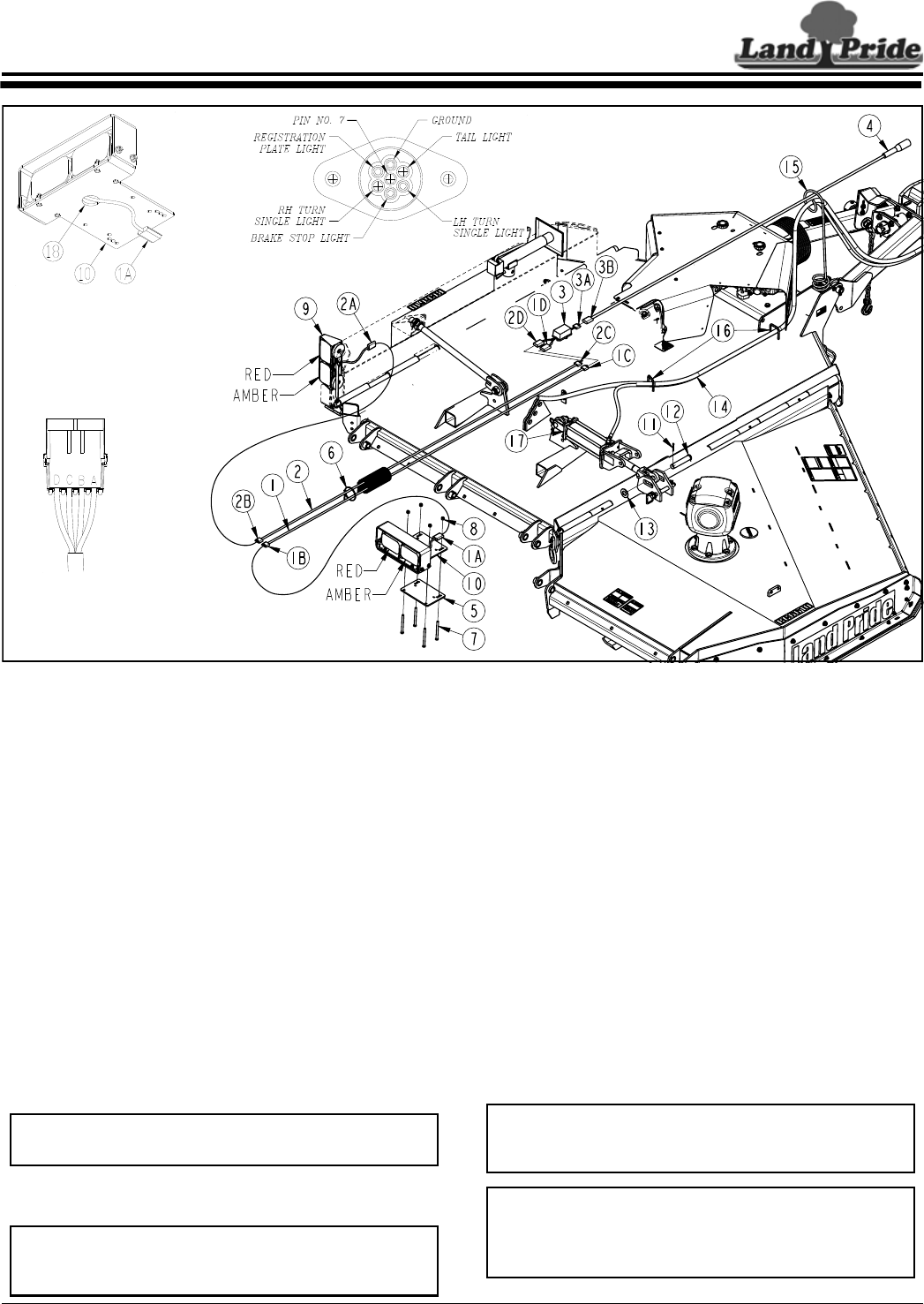
Light Kit Option (LED)
331-683A Folding Cutter Light Kit 3 1/2"
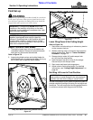
Refer to Figure 4-1:
The lead wiring harness (#4) is equipped with a 7-way
round pin connector. Make sure your tractor is equipped
with the 7-pin electrical outlet shown in Detail C before
purchasing this product.
1. Lower cutter center deck and wing deck down until
unit is resting on the lift cylinder stops and both wings
are on the ground.
2. Shut tractor down properly before dismounting. Refer
to “Tractor Shutdown Procedure” on page 14.
3. Before dismounting, move hydraulic control levers
back and forth several times to release all hydraulic
pressure in hydraulic lines to the cutter.
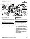
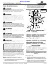
4. On the right-hand wing, remove cotter pin (#11), flat
washer (#13), and clevis pin (#12).
5. If not already done, thread connector (#1A) through
hole (#18) as shown in Detail A.
NOTE: Hydraulic hose (#14) must be located above
light assembly (#10) as shown.
NOTE: Amber and red lights are located as shown
with two lamps facing back and one lamp facing
forward on each light assembly.
6. Attach right-hand light assembly (#10) above
hydraulic cylinder (#17) with mounting clamp (#5)
under the hydraulic cylinder.
7. Nuts (#8) must be on top. Secure unit with
3/8"-16 x 5" GR5 bolts (#7) and locknuts (#8). Draw
locknuts up snug, do not tighten at this time.
8. Replace clevis pin (#12) and secure with flat
washer (#13) and cotter pin (#11). Bend one or more
legs of cotter pin to keep pin from falling out.
9. Slide light assembly (#10) and mounting clamp (#5)
as far as possible toward the rod end of hydraulic
cylinder (#17).
10. Tighten each lock nut (#8) one-half turn in a criss-
cross pattern until all nuts are tightened to the correct
torque.
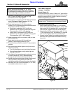
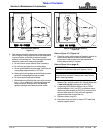
11. Locate magnetic light assembly (#9) outside of
weight box as shown.
NOTE: Right-hand wire harness (#1) has a red wire
showing at both ends. Left-hand harness (#2) has a
yellow wire showing at both ends.
NOTE: See Detail B: Pins in connectors are labeled
A, B, C, & D. Match yellow and red wires with same
pin letters when attaching wire harness to light
assemblies (#9 & #10) & enhance module (#3).
Light Kit (Shown on RC5610 Deck)
Figure 4-1
Detail B
Detail C
Detail A
37842
Section 4: Options & Accessories