


45
Section 5: Maintenance & Lubrication
11/11/12
RCB6610 & RCBM6610 Series 2 S/N 944730+ Rotary Cutters 330-584M
Table of Contents
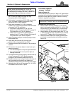
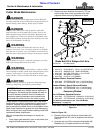
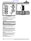
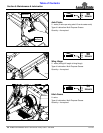
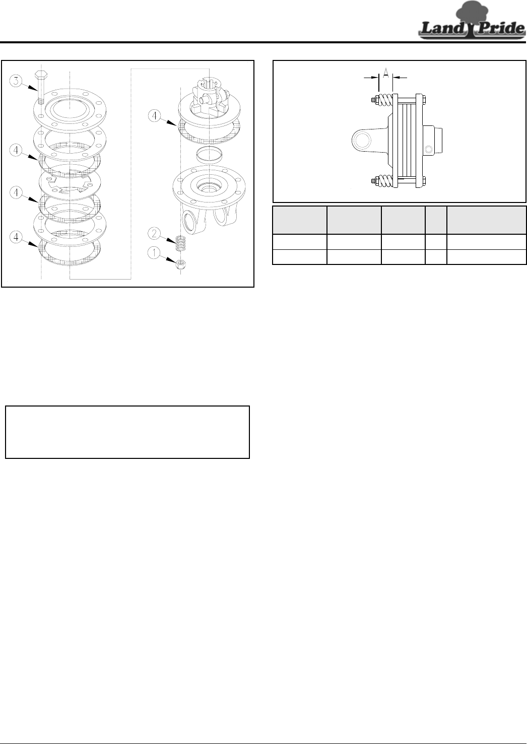
Type A Clutch Assembly
Figure 5-11
Clutch Disassembly, Inspection & Assembly
Refer to Figure 5-11:
If clutch run-in procedure above indicated that one or more
friction disks did not slip, then the clutch must be
disassembled to separate the friction disks.
Disassembly
Disassembly of clutch is simply a matter of first removing
spring retainer nuts (#1), springs (#2), and bolts (#3) from
the assembly. Each friction disk (#4) must then be
separated from the metal surface adjacent to it.
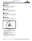
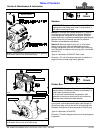
Inspection
Inspect all parts for excessive wear and condition. Clean
all parts that do not require replacement.The original
friction disk thickness is 1/8" (3.2mm) and should be
replaced if thickness falls below 3/64" (1.1mm). If
clutches have been slipped to the point of “smoking”, the
friction disks may be damaged and should be replaced.
Heat build-up may also affect the yoke joints.
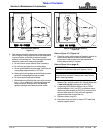
Assembly
Reassemble each friction disk (#4) next to the metal plate
it was separated from. Install bolts (#3) through end
plates and intermediate plates as shown. Place
springs (#2) over the bolts and secure with nuts (#1).
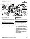
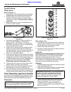
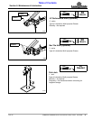
Refer to Figure 5-12:
Progressively tighten each spring retainer bolt until
correct spring height “A” is reached.
23554
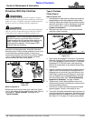
IMPORTANT: Not all clutches are assembled the
same with the same number of components. Be sure
to keep track of order and orientation of your clutch
components during disassembly.
g
Type A Clutch Adjustment
Figure 5-12
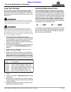
Driveline
No.
Driveline
Location
PTO
Speed
Cat
No.
A (inches)
Spring Height
826-818C Center 540/1000 5 1.32"
826-812C Wing 540/1000 5 1.32"
24600