


37
Section 4: Options & Accessories
11/11/12
RCB6610 & RCBM6610 Series 2 S/N 944730+ Rotary Cutters 330-584M
Table of Contents
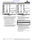
12. Red wires in connectors (#1A & #1B) are attached to
pin “D” shown in Detail B on page 36. Plug
connectors (#1A & #1B) together.
13. Yellow wires in connectors (#2A & #2B) are attached
to pin “B” shown in Detail B on page 36. Plug
connectors (#2A & #2B) together.
14. Route wire harnesses (#1 & #2) to enhance
module (#3). Plug connectors at the enhance module
to harness (#1 & #2) as follows:
a. Red wires in connectors (#1C & #1D) are
attached to pin “B” shown in Detail B on page 36.
Plug connectors (#1C & #1D) together.
b. Yellow wires in connectors (#2C & #2D) are
attached to pin “C” shown in Detail B on page 36
Plug connectors (#2C & #2D) together.
15. Attach connector (#3A) to connector (#3B) on lead
wire harness (#4).
16. Route lead wire harness (#4) through hose
guides (#16) and spring hose loop (#15).
17. Connect harness (#4) to the tractor’s 7-way round pin
receiver.
18. Start tractor and operate lights to verify hook-up is
operating properly:
a. Turn on head lights to verify red lights illuminate.
b. Turn on flasher lights to verify amber light are
blinking on and off.
19. If the lights did not operate properly, recheck hook-up
of wire harnesses (#1 & #2). Make necessary
changes to the harnesses and repeat step 18.
20. Recheck wire harness routing to make sure wires will
not be pinched as wing decks are folded and
unfolded and while raising and lowering cutter height.
21. Add cable ties (#6) to wire harnesses (#1, #2, & #4)
as needed to secure them in place.
NOTE: Route wire harnesses (#1, #2, & #4)
alongside hydraulic hoses. Make sure harnesses
will not become pinched as the deck is raised and
lowered and wings are folded up and down.
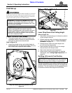
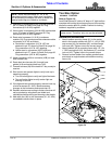
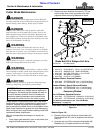
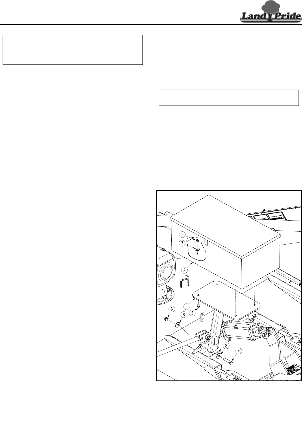
Tool Box Option
330-869A TOOLBOX
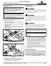
Refer to Figure 4-2:
Land Pride offers a 30" wide x 16" deep x 12" high tool box
complete with locking lid and support mount for mounting
above the center deck lift cylinder. Padlock for locking
toolbox is supplied by customer.
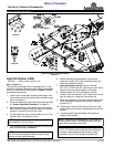
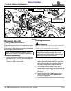
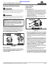
Installation Instructions
1. Attach toolbox mounting frame (#1) to the center
deck in the location shown with 5/8"-11 x 2 3/4" GR5
cap screws (#4), flat washers (#8), and hex flange
lock nuts (#6). Tighten nuts to the correct torque.
2. Attach toolbox (#2) to mounting frame with 1/2"-13 x
1" GR5 carriage bolt (#3), flat washers (#7), and hex
lock nut (#5). Tighten nuts to the correct torque.
3. Remove manual holder from splitter gearbox cover
and attach to angle brackets on toolbox mounting
frame (#1).
Tool Box Option
Figure 4-2
NOTE: Tool Box and Mechanical Winch use the
same mount. Therefore, only one can be selected.
33274