


14
Section 1: Assembly & Set-up
RCB6610 & RCBM6610 Series 2 S/N 944730+ Rotary Cutters 330-584M
11/11/12
Table of Contents
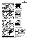
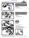
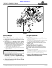
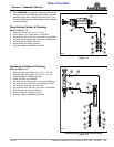
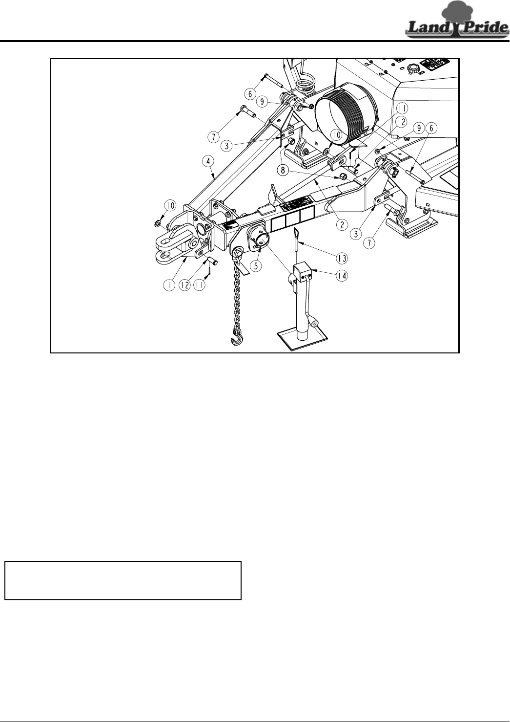
Hitch Assembly
Refer to Figure 1-7:
1. Remove and discard 1/2" nuts (#9) and bolts (#6).
2. Rotate hitch (#4) down into pulling position as shown
in Figure 1-7.
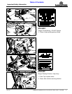
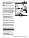
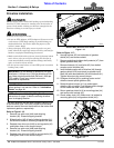
3. Instructions “a” & “b” below are for cutters equipped
with standard clevis or pintle hitch. Skip to step 4 if
assembling LP Performance, bar-tite, or ball hitch.
a. Attach clevis level rod (#2) to center deck lug and
clevis hitch (#1) with clevis pins (#12), flat
washers (#10), and cotter pins (#11).
b. Secure cotter pins (#11) by bending one or more
legs of each pin.
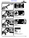
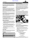
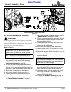
4. Attach hitch frame (#4) to leveling rods (#3) by
inserting 3/4" x 3" lg. bolts (#7) through leveling rod’s
outside clevis plate, hitch frame (#4), and out through
leveling rod’s inside clevis plate. Secure bolts with
nylock nut (#8). Draw nuts up snug, do not tighten.
5. Leveling rod adjustment will be made after the cutter
is attached to the tractor.
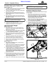
IMPORTANT: Insert bolts (#7) from outside the hitch
frame. Inserting bolts from inside the hitch will result
in them interfering with tractor tires.
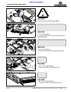
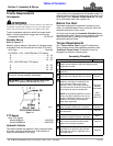
Park Jack Assembly
Refer to Figure 1-7:
1. Attach park jack (#14) to jack mount (#5) and secure
with detent pin (#13).
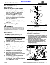
2. If park jack is not vertical, adjust jack angle according
to “Park Jack Angle Alignment” on page 26.
3. Adjust jack up or down until clevis hitch (#1) is at
drawbar height.
Tractor Shutdown Procedure
The following is proper tractor shutdown procedures.
Always follows these procedures before dismounting
tractor.
1. If engaged, disengage PTO.
2. Lower attached implement to ground, put tractor in
park or set park brake, turn off engine, and remove
switch key to prevent unauthorized starting.
3. Wait for all cutter components to come to a complete
stop before leaving the operator’s seat.
Hitch & Jack Assembly
Figure 1-7
37612