


17
Section 1: Assembly & Set-up
11/11/12
RCB6610 & RCBM6610 Series 2 S/N 944730+ Rotary Cutters 330-584M
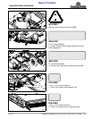
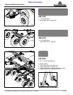
Table of Contents
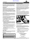
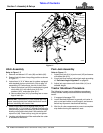
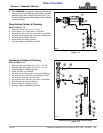
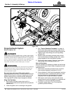
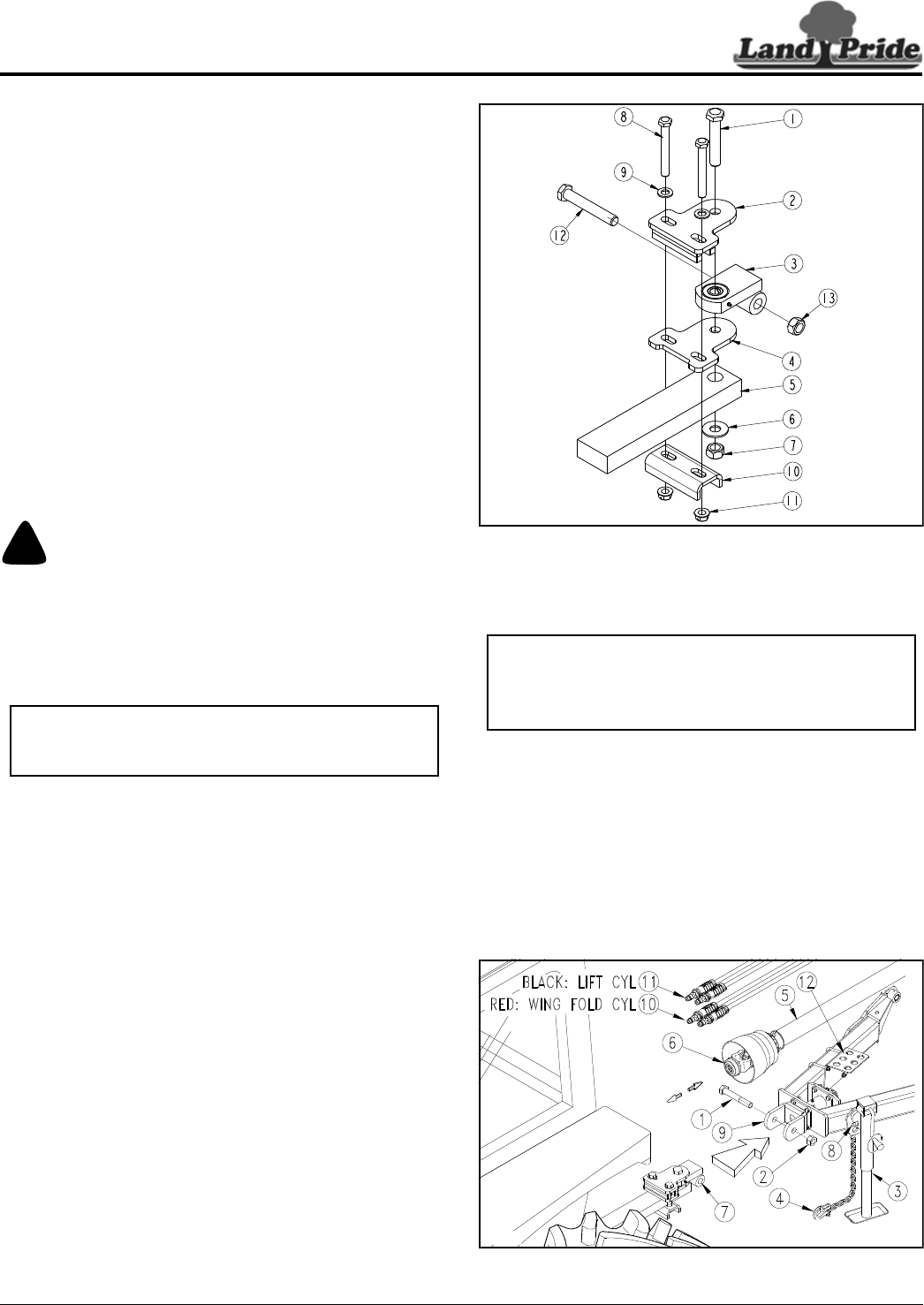
Bar-Tite Hitch Hook-up
Refer to Figure 1-10:
Attach Bar-Tite Hitch to Tractor Drawbar
1. Insert 1" x 5 1/2" hex bolt (#1) through hitch top
plate (#2), hitch bushing (#3), hitch wear plate (#4),
tractor drawbar (#5), and washer (#6) as shown.
Secure with 1" lock nut (#7). Tighten 1" lock nut
snugly to remove all play and then back nut
one-quarter turn. Do Not torque 1" lock nut.
2. Insert two 3/4" x 6" GR5 hex bolts (#8) through,
3/4" flat washers (#9), hitch top plate (#2), hitch wear
plate (#4), and formed hitch support (#10) as shown.
Secure with 3/4" locknuts (#11).
3. Tighten 3/4" locknuts to correct torque.
4. Remove 1" x 6 1/2" GR5 hex bolt (#12) and 1" lock
nut (#13) from hitch bushing (#3). Keep bolt and lock
nut for reuse.
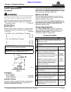
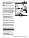
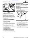
Attach Tractor to Rotary Cutter
!
DANGER
A Crushing Hazard exists when hooking-up equipment to a
tractor. Do not allow anyone to stand between tractor and
implement while backing-up to implement. Do not operate
hydraulic 3-Point lift controls while someone is directly
behind the tractor or near the implement.
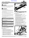
Refer to Figure 1-11:
1. Make certain park jack (#3) is properly attached to
cutter hitch and secured with detent pin (#8). If park
jack is not vertical, refer to “Park Jack Angle
Alignment” on page 26.
2. Store center 3-point link in the tractor storage hook.
3. Start tractor and raise 3-point arms fully up.
4. Carefully back tractor within close proximity of
clevis (#9).
5. Shut tractor down properly before dismounting. Refer
to “Tractor Shutdown Procedure” on page 14.
6. Verify tractor drawbar is adjusted correctly. Refer to
“Drawbar Set-up” dimensions on page 12.
7. Raise or lower park jack (#3) to align swivel
clevis (#9) with bolt hole in hitch bushing (#7).
8. Restart tractor and back tractor up to swivel
clevis (#9) until hole in hitch bushing (#10) aligns with
holes in swivel clevis (#9).
9. Shut tractor down properly before dismounting.
10. Insert 1" x 6 1/2" GR5 hex bolt (#1) through swivel
clevis (#9) and hitch bushing (#7). Secure hex bolt
with lock nut (#2). Tighten lock nut snugly to remove
all play. Do Not torque 1" lock nut.
IMPORTANT: Ball detent pin (#8) must be fully
inserted in park jack (#3) before working on or
around a cutter not hooked to a tractor drawbar.
Bar-Tite Hitch Assembly to Tractor Tongue
Figure 1-10
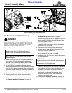
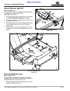
11. Lower park jack (#3) until hitch weight is supported
by the drawbar.
12. Remove park jack (#3) from the hitch and attach it to
the weight box with detent pin (#8). Make sure jack
base is level or lower than the jack crank head. See
cover picture for correct positioning.
13. Attach hitch safety chain (#4) to the tractor. Adjust
chain length to remove all slack except what is
necessary to permit turning. Securely lock chain
hook to the safety chain.
14. Continue with “Hydraulic Plumbing” on page 18
and “Driveline Installation” on page 20.
Tractor Hookup to Bar-Tite Hitch
Figure 1-11
22265
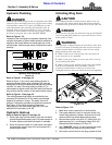
IMPORTANT: Protect park jack by attaching it to the
weight box before moving the cutter. Make sure jack
is stored with its base level or lower than the head to
prevent water and freeze damage.
35549