


B - Performance Test and Calibration
82
Pulse Width Accuracy
This test verifies that the transient generator pulse width accuracy is within specification. Note: Use the GPIB controller to
generate a continuous pulse train.
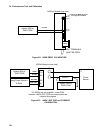
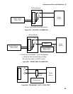
1. Connect Electronic Load, Power Source, Current Probe and Oscilloscope as shown in figure B-5.
2. If using a controller, connect controller to Electronic Load mainframe rear panel GPIB connector.
3. Turn on the Electronic Load and press [Recall]. Scroll to until *RST is displayed and press [Enter].
4. Turn on the Power Source and program the voltage to 10 V and the current to 15 A.
5. Turn on the Oscilloscope and set to:
a. Ch 1 vertical deflection, 15 mV/div.
b. 1:1 probe, DC coupled, 50 Ohms.
c. Position or offset to 50mV.
d. Horizontal time base to 20 uS/div.
e. Trigger on positive edge at about 50mV.
6. Turn on Current Probe to the 10mV/A position.
7. Run the following program for a continuous pulse train or skip to step 8 to manually generate pulses.
10 OUTPUT 705;”*RST”
20 OUTPUT 705;”TRAN:MODE PULS”
30 OUTPUT 705;”CURR:TLEV 10”
40 OUTPUT 705;”TRAN:TWID 100E-6”
50 OUTPUT 705;”TRAN ON”
60 OUTPUT 705;”TRIG:IMM”
70 WAIT 1000 ! wait 1 second
80 GOTO 60 ! loop back to line 60 to for continuous pulse train.
90 END
8. For front panel single pulse operation: (Note: skip to step 9 if using a controller to generate a continuous pulse train)
a. Press [Current] and scroll to C:TLEV. On the Entry keypad press 10 [Enter].
b. Press [Tran] and scroll to T:TWID. On the Entry keypad enter 1E-4 then [Enter] to generate a pulse width of
100uS.
c. Press [Tran] and scroll to T:MODE. On the Entry keypad scroll to T:MODE PULS then press [Enter] .
d. Press [Tran]. Using the Entry keypad scroll to ON and press [Enter] to activate the transient mode.
e. Press [Trigger Control] and then [Enter] to initiate the trigger system.
f. Press [Shift] and then [Trigger] to generate a single current pulse from zero to 10 A..
9. Adjust the oscilloscope as needed to display a complete pulse waveform. Generate pulses as needed.
10. Measure width of the 10 A, 100 uS nominal pulse between the 50% points of waveform and record the results on
Performance Test Record. Note: Use the built-in measurement capabilities of the oscilloscope, if available, for the most
accurate results.