


General Information - 2
29
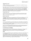
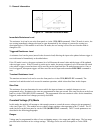
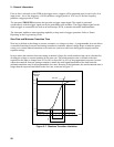
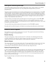
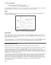
Therefore, both minimum transition time and slew rate must be considered when determining the actual
transition time. This is shown in Figure 2-8, which shows the minimum transition time for a given slew rate as a
horizontal line, and at about a 13.3% or greater load change, the slew rate increases from the minimum
transition time to the Maximum transition time at a 100% load change. The actual transition time will be either
the minimum transition time, or the total slew time (transition divided by slew rate), whichever is longer.
Use the following formula to calculate the minimum transition time (MinTT) for a given slew rate:
MinTT (in seconds) =
__________8__________
slew rate (in amps/second)
Use the following formula to calculate the maximum transition time (MaxTT) for a given slew rate:
MaxTT (in seconds) =
__________60__________
slew rate (in amps/second)
NOTE: In voltage mode, all minimum transition times are based on a low-capacitance current source.
These transition times are affected by capacitive loading of the inputs. For example, a
capacitance of 2.2 microfarads increases the 85 microsecond minimum transition time (shown
in the table) to 110 microseconds.
8000
µ
s
800
µ
s
80
µ
s
12
µ
s
60000
µ
s
6000
µ
s
600
µ
s
60
µ
s
16
µ
s
S
lo
w
est
S
lew Rate
S
lew
Rat
e A
Slew Rate B
S
lew
Rat
e C
F
a
s
t
e
s
t
Minimum
Transition
Time
Maximum
∆
∆ ∆
∆
Time
∆
∆ ∆
∆
Current (% of full scale)
5%
13.3% 16.7%
50% 100%
A.
8000
µ
s
800
µ
s
85
µ
s
60000
µ
s
6000
µ
s
600
µ
s
S
lo
w
est
S
lew Rate
S
lew
Rat
e A
Slew Rate B
Minimum
Transition
Time
Maximum
∆
∆ ∆
∆
Time
∆
∆ ∆
∆
Voltage (% of full scale)
5%
13.3% 16.7%
50% 100%
120
µ
s
F
astest
B.
Figure 2-8. Transition Time Slew Rate Examples