


B - Performance Test and Calibration
76
Performance Tests
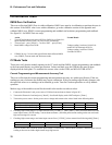
IMON Zero Verification
This test verifies that IMON Zero is within calibration. IMON zero must be in calibration to perform the tests in
this section. If the IMON value is not within calibration, go to the calibration section of this appendix and
calibrate IMON zero, IPROG, current programming and readback and resistance programming and readback.
See figure B-1 for IMON Zero test setup.
Action Normal Result
1. Turn off load module and connect DVM to IMON as per figure B-1.
Input terminals must be open ( no power source connected )
2. Turn on Load – press [ Recall } – scroll to *RST – press [Enter ]
3. Read IMON voltage from DVM. Voltage reading less than 0.166mV for
models N3302A through N3305A
Voltage reading less than 0.320mV
for model N3306A
4. If IMON in step 3 in not within specification then calibrate IMON
zero, IPROG, Current mode and Resistance mode.
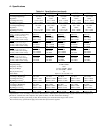
CC Mode Tests
These tests verify that the module operates in the CC mode and that IMON, current programming, and readback
to the front panel display are within specification. Values read back over the GPIB are the same as those
displayed on the front panel. To read back the current value via the GPIB, use MEAS:CURR:ACDC?
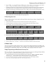
Current Programming and Measurement Accuracy Test
This test verifies that the current programming and measurement accuracy are within specification. If the test
readings are out of tolerance the module may require calibration. If the test readings significantly disagree with
the specified values or no readings can be obtained go to the Turn-On Checkout procedure to verify module
operation.
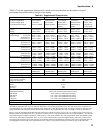
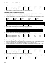
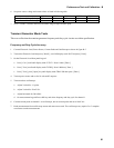
Make a copy of the module test card for the model to be tested to record test values.
1. Connect the Electronic Load, power source, DVM and current shunt as shown in figure B-2.
2. Turn on the Electronic Load and press [ Recall ]. Scroll until display reads *RST and press [ Enter ].
3. Turn on the power source. Set the power source voltage and current to the values listed in the following table.
N3302A N3303A N3304A N3305A N3306A
Power Source Voltage Setting 5V 20V 5V 8V 5V
Power Source Current Setting 33A 12A 61A 61A 130A
4. Checking high current range, Low input current. Press [ CURR ] [ 1 ] then [ Enter ]. Wait 10 seconds then record the
actual input current ( DVM reading / current shunt resistance ) and front panel current reading on the test card under
high current range low current.
5. Checking high current range, maximum input current. Press [ CURR ] [ select current from following table] [Enter ].
N3302A N3303A N3304A N3305A N3306A
30 10 60 60 120
Wait 30 seconds, then record the actual input current ( DVM reading / current shunt resistance ) and front panel current
reading on the test card under high current range high current.