


Installation - 3
47
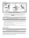
Sense Switch
A local/remote sense switch is provided on each module. Unless you are using remote sensing, make sure that
the sense switch is set to LCL (depressed). Remote sensing is used in certain applications to achieve greater
accuracy (refer to Remote Sense Connections for more information).
NOTE If the sense switch is set to remote operation without having sense leads connected to the sense
inputs, the module will continue to work in the CC mode, but the input will turn off in CV and
CR modes. Voltage readback will not work in any mode.
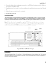
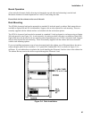
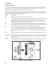
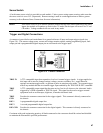
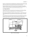
Trigger and Digital Connections
A connector is provided on each mainframe for a ground reference of input and output trigger signals (see
Figure 3-8). The remote voltage sense, current and voltage monitor signals, analog programming input, fault
output pin and a programmable digital output pin are referenced to the trigger input.
Figure 3-8. Control Connector
TRIG IN
A TTL-compatible input that responds to low-level external trigger signals. A trigger applied to
this input can be used to change settings (voltage, current, resistance, etc.), toggle between
settings in transient-toggle mode, or generate a pulse in transient-pulse mode. An external trigger
affects any module that has its external trigger input enabled by the TRIG:SOUR:EXT command.
TRIG
OUT
A TTL-compatible output signal that becomes active (low-level) whenever the electronic load is
triggered by a GPIB command or TRIG IN signal. This signal can be used to trigger external
equipment such as oscilloscopes, digitizers, or another electronic load.
TRIG
GND
Provides the common connection for the trigger signals. This common is directly connected to
the chassis.
DIG 1
A programmable digital output line.
DIG 2
A second programmable digital output line.
DIG GND
Provides the common connection for the digital signals. This common is directly connected to
the chassis.
Consistent with good engineering practice, all leads connected to the connector should be twisted and shielded
to maintain the instrument's specified performance.