


Performance Test and Calibration - B
77
6. Press [ CURR ] [ 1 ] ( except N3303A press [ CURR ] [ 0.1 ] ). Press [ CURR ]. Scroll until display reads C:RANG,
press [ 1 ] [ Enter ]. Press shift key, [ Sense ] scroll till display reads S:C:RNG press [ 1 ] [ Enter ].
7. Checking low current range, low input current Wait 10 seconds then record the actual input current ( DVM reading /
current shunt resistance ) and front panel current reading on the test card under low current range low current.
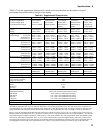
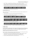
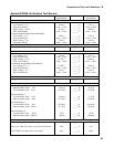
8. Checking low current range, maximum input current. Press [ CURR ] [ select current from following table ] [ Enter ].
N3302A N3303A N3304A N3305A N3306A
3166 12
Wait 30 seconds then record the actual input current ( DVM reading / current shunt resistance ) and front panel
current reading on the test card under high current range high current.
CC Mode Regulation Test
This test verifies the Input Current remains within specification when the input voltage is changed from a low
voltage to rated voltage.
1. Connect the Electronic Load, power source, DVM and current shunt as shown in figure B-2.
2. Turn on the Electronic Load and press [ Recall ]. Scroll until display reads *RST and press [ Enter ]
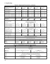
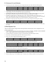
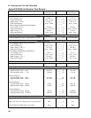
3. Press [ CURR ] [ select current from following table ] [ Enter ].
N3302A N3303A N3304A N3305A N3306A
2.5 1 5 3.3 10
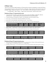
4. Turn on the power source. Set the power source voltage and current to the values listed in following table.
N3302A N3303A N3304A N3305A N3306A
Power Source Voltage Setting 4V 4V 4V 4V 4V
Power Source Current Setting 5A 5A 10A 10A 20A
5. Wait 10 seconds, then record input current reading ( DVM reading / current shunt ).
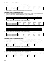
6. Reset the power source voltage level to value listed in following table.
N3302A N3303A N3304A N3305A N3306A
Power Source Voltage Setting 60V 240V 60V 150V 60V
7. Wait 10 seconds, then record input current reading ( DVM reading / shunt resistance ).
8. Subtract reading in step ‘7’ from step ‘5’. Absolute value of difference should be less then specification.
CV Mode Tests
These tests verify that the module operates in the CV mode and that voltage programming and readback to the
front panel display are within specification. Values read back over the GPIB are the same as those displayed on
the front panel. To read back the voltage value via the GPIB, use the command MEAS:VOLT:ACDC?
Voltage Programming and Measurement Accuracy Test
This test verifies that voltage programming and voltage measurement accuracy are within specification. Make a
copy of the module test card for the model being tested to record test values.
1. Connect the Electronic Load, Power source and DVM as shown in figure B-3. Be sure + sense and – sense are
connected to the +/- input terminals and the remote/local button is in the remote position.
2. Turn on the Electronic Load and press [ Recall ]. Scroll until display reads *RST and press [ Enter ].
3. Press [ Func ]. Scroll until display reads FUNC VOLT then press [ Enter ].