


General Information - 2
33
Saving and Recalling Settings
The electronic load has internal registers in which settings (mode, current, voltage, resistance, slew, transient
level, etc.) for each module can be saved. By saving settings and recalling them later you can save
programming time.
The present settings for all channels are saved in the specified register (0 to 9) at the front panel or via the GPIB
(*SAV command). All of the settings are saved in the specified location in the mainframe's memory. Settings
saved in locations 1 through 6 will be lost when ac line power is cycled. However, the *SAV 0 command will
cause the settings to be stored in a non-volatile memory; and, the next time the electronic load is turned on, these
settings will become the power-on settings. In addition, locations 7 through 9 are also saved in non-volatile
memory. These locations are used to store lists.
You can recall the saved settings from the specified register (0 to 9) at the front panel or via the GPIB (*RCL
command). All of the parameters for each module which were saved by the *SAV command are set to the
saved values. At power-on, the electronic load automatically executes a *RCL 0, which recalls the values saved
in location 0 of non-volatile memory.
You can recall the factory default settings at the front panel or via the GPIB (*RST command).
Remember that Save and Recall operate on all channels, not just the presently addressed or selected channel.
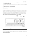
External Control Signals
Each module has a 14-pin connector mounted on its rear panel. These signals are described in the following
paragraphs. See Chapter 3 for connection details.
Remote Sensing
The remote sensing inputs, + S and - S, can be used in CV or CR modes. By eliminating the effect of the
inevitable voltage drop in the load leads, remote sensing provides greater accuracy by allowing the load to
regulate directly at the source's output terminals, as well as measure the voltage there.
Monitor Outputs
The current monitor (pin A1) and voltage monitor (pin A2) output signals indicate the input current and voltage.
A 0-to-+10V signal at the appropriate output indicates the zero-to-full scale input current or voltage. An
external DVM or oscilloscope can be connected to monitor the input voltage and current.
External Programming Input
CC and CV modes can be programmed with a signal (ac or dc) connected to the external programming (pin A4)
input. A 0-to-10V external signal corresponds to the 0-to-full scale input range in CV mode or in CC mode.
The external programming signal is combined with the value programmed via the GPIB or the front panel, so
that, for example, a programmed value of one-half full scale and a 5-volt external programming input would
produce a full-scale value at the input.
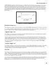
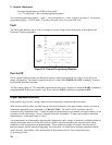
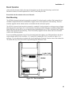
Figure 2-9 shows the input waveform that would result from the following setup:
CC Mode
60A Range