


Installation - 3
39
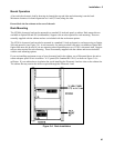
6. Connect the ribbon cable to the adjacent connector pins in the GPIB board (or adjacent module). Make sure
the connectors are properly seated.
7. If applicable, install each module in the slot next to the previous module in the same manner (step 3 through
6).
8. Replace the top cover after all modules are installed.
9. Reconnect the power cord.
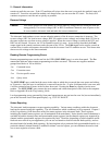
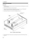
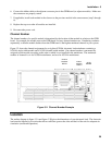
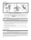
Channel Number
The channel number of a specific module is determined by the location of that module in relation to the GPIB
board. For example, the module next to the GPIB board is always channel number one. Numbering continues
sequentially so that the module furthest from the GPIB board is the highest numbered channel in your system.
Figure 3-2 shows the channel assignments for an Agilent N3300A electronic load mainframe containing a
N3304A single-width module and a N3305A double-width module. One channel number is automatically
assigned to each module according to the order in which it was installed in the mainframe. The maximum
number of channels is six for N3300A mainframes, and two for N3301A mainframes.
GP-IB
BOARD
CHAN 1
SINGLE
WIDTH
CHAN 2
DOUBLE
WIDTH
Figure 3-2. Channel Number Example
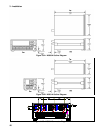
Location
The outline diagram in figure 3-3A and figure 3-3B gives the dimensions of your electronic load. The electronic
load must be installed in a location that allows sufficient space at the sides and back of the unit for adequate air
circulation (see Bench Operation).