


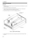
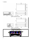
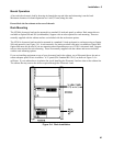

3 - Installation
46
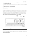
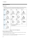
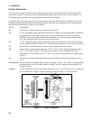
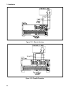
Control Connector
A 14-pin connector and a quick-disconnect mating plug are provided on each module for connecting remote
sense leads, external V/I monitors, an external programming input, and external control lines (see figure 3-7).
The mating plug is packaged in an envelope that is included with the module.
Consistent with good engineering practice, all leads connected to the control connector should be twisted and
shielded to maintain the instrument's specified performance. Make all wire connections to the mating plug as
required before installing the connector in the module.
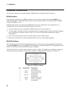
A1-A3
Not available
A4
Provides the common connection for the A5 and A6 pins.
A5
A TTL-compatible output signal that becomes active (high level) when the PORT0 command is
programmed ON. This signal can be used to control an external device such as a relay for
shorting or disconnecting the module's input terminals or as a general purpose digital output
port. This signal powers up in the inactive (low-level) state.
A6
A TTL-compatible output (fault) signal that becomes active (high level) when an overvoltage,
reverse voltage condition or fault occurs. This signal powers up in the inactive (low-level) state.
A7
Provides the common connection for the external programming input (pin A8).
A8
Connects an external programming input. The CC and CV mode can be programmed with a
0V-to-+10V signal (ac or dc). This signal can act alone or can be combined with values
programmed over the GPIB or RS-232. Thus, it is possible to superimpose an ac signal upon a
dc level.
A9
Provides the common connection for the current and voltage monitor signals (pins A10 and
A11).
A11 and A10
Used to monitor the modules input current and voltage. A 0V-to-+10V signal at the appropriate
pin indicates the zero-to-full scale current or voltage. Pin A11 monitors current and pin A10
monitors voltage.
+S and -S
Used to connect the remote sense leads to the power source. Pin +S connects the +S signal and
pin -S connects the -S signal. Remote sensing can only be used in CV and CR modes.
Figure 3-7. Control Connector