


Performance Test and Calibration - B
79
CR Mode Tests
These tests verify that the module operates in CR mode and the resistance programming is within specification.
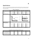
The programmed resistance values are checked by recording the voltage across the current monitor resistor and
the input voltage (voltage at the modules + and – sense terminals ), then calculating the resistance as follows;
Load Resistance = Input Voltage / ( voltage across current monitor / monitor resistor value )
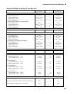
Resistance Range 1 Programming Accuracy
1. Connect Electronic Load, Power source and DVM’s as shown in figure B-4. Be sure + sense and – sense are
connected to the +/- input terminals and the remote/local button is in the remote position.
2. Turn on the Electronic Load and press [ Recall ], scroll till display reads *RST and press [ Enter ].
3. Press [ Func ]. Scroll until display reads FUNC RES then press [ Enter ].
4. Press [ RES ]. Scroll until display reads RES:RANG, press [ 1 ] then [ Enter ].
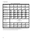
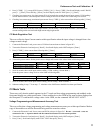
5. Turn on the power source. See power source voltage and current values as listed in following table.
N3302A N3303A N3304A N3305A N3306A
Power Source Voltage Setting 24V 48V 12V 30V 15V
Power Source Current Setting 7A 7A 10A 10A 20A
6. Wait 30 seconds. Checking resistance range 1, high resistance point. Calculate and record resistance on test card.
Input resistance = Input Voltage / ( DVM voltage reading from current shunt/ current shunt resistance).
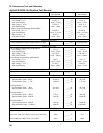
7. Checking resistance range 1, low resistance point. Reset power source voltage to following values.
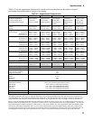
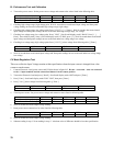
N3302A N3303A N3304A N3305A N3306A
Power Source Voltage Setting 4V 6V 10V 5V 6V
Power Source Current Setting 25A 10A 30A 50A 70A
8. Press [ RES ] [ select resistance from following table ] [ Enter ].
N3302A N3303A N3304A N3305A N3306A
0.2Ω 1.2 Ω 0.5 Ω 0.125 Ω 0.100 Ω
9. Wait 30 seconds. Calculate and record resistance range 1, low resistance point.
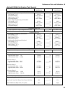
Resistance Range 2 Programming Accuracy
1. Press [ RES ]. Scroll until display reads RES:RANG, For models N3302A, N3304A, N3305A and N3306A press
[ 9 ] then [ Enter ]. For model N3303A Press [ 5 ] [ 0 ] then [ Enter ].
2. Checking resistance range 2, low resistance point. Press [ RES ] [select resistance from following table ] [ Enter ].
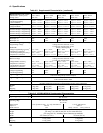
N3302A N3303A N3304A N3305A N3306A
3.6 Ω 44 Ω 1.8 Ω 4.5 Ω 0.9 Ω
3. Set power source voltage and current values as listed in following table.
N3302A N3303A N3304A N3305A N3306A
Power Source Voltage Setting 20V 96V 6V 30V 6V
Power Source Current Setting 7A 3A 7A 15A 8A
4. Wait 15 seconds. Calculate and record resistance range 2 low resistance point.
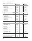
5. Checking resistance range 2, high resistance point. Press [ RES ] [select resistance from following table ] [ Enter ].
N3302A N3303A N3304A N3305A N3306A
40 Ω 480 Ω 20 Ω 50 Ω 10 Ω