


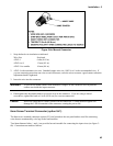

Installation - 3
43
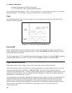
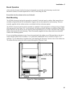
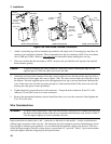
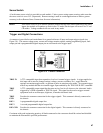
Figure 3-6a. Manual Connector
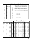
1. Strip the back wire insulation as indicated
Wire Size Strip back
AWG 4 6 mm (0.65 in)
AWG 6 or 8 13 mm (0.5 in)
AWG 10 or smaller 10 mm (0.4 in)
2. AWG 4 is the maximum wire size. Stranded copper wire size, AWG 6 or 8 is the recommended wire. If
you are connecting more than one wire on each connector, twist the wires to ensure a good contact when the
adjustment knob is tightened.
3. Insert the wire into the connector.
WARNING To prevent accidental contact with hazardous voltages, do not extend the wire beyond the
contact area inside the input connector.
4. Hand-tighten the adjustment knob to secure the wire in the connector. If you are using a slotted
screwdriver, tighten the knob to 8 in-lb (90 N-cm) for a secure connection.
Caution Do not use lubricants or contact cleaners on the connectors. Certain chemical agents can
damage the LEXAN material of the connector, causing the part to fail.
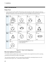
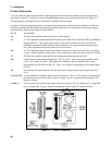
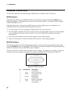
8mm Screw Terminal Connector (option UJ1)
The 8mm screw terminal connectors (option UJ1) are located on the rear panel and are used for connecting
wires that are terminated by wire lugs to the load modules.
Two 8mm-diameter bolts (+ and −) are provided on each module for connecting the input wires (see figure 3-
6b). Connections are made as follows: