


3 - Installation
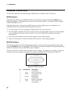
44
spacer
wires exiting at topwires exiting at bottom
safety cover secured
spacer
insulated
wire lug
(AMP 52266-3)
4 AWG
wire max.
tighten
cover
screw
insert
tabs
spacer
(0380-4835)
conical
washer
(3050-1924)
breakaway
tab
cover
(5040-1736)
connector
assembly
with bolt
(5040-1739)
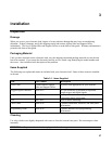
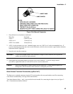
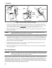
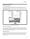
Figure 3-6b. 8mm Screw Terminal Connectors
1. Attach a connecting lug with an insulated ring terminal to the input wires. Connecting lugs must have an
opening of at least 8mm in diameter. The recommended wire lug for connecting AWG 4 wire to an 8mm
stud is AMP p/n 52266-3. Refer to www.amp.com for information about ordering this wire lug.
2. Wire sizes smaller than the maximum of AWG 4 may be used, provided the wire lugs have the required
8mm diameter opening.
Caution To prevent damaging the wiring insulation, which may result in shorting the input, use the
supplied spacer to offset the input wires from each other.
3. Attach the wire lugs to the connector. Place the conical washer between the bolt and the wire lug (refer to
the exploded view in the upper left corner of figure 3-6b). The wires can exit either out of the top or out of
the bottom. Place the supplied spacer under the appropriate wire lug to prevent interference between the
wires. If the wires exit out of the top, place the spacer on the bottom terminal. If the wires exit out of the
bottom, place the spacer on the top terminal.
4. Tighten the bolts to secure the wires to the connectors. Torque the bolts to between 20 and 25 in-lbs
(between 225 and 280 N-cm) for a secure connection.
5. Remove the appropriate breakaway tab and install the safety cover over the connectors. Hand-tighten the
Torx T10 cover screw.
Wire Considerations
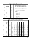
WARNING To satisfy safety requirements, load wires must be heavy enough not to overheat while carrying
the short-circuit output current of the device connected to the electronic load. Refer to Table 3-
2 for the ampere capacity of various stranded wire sizes.
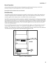
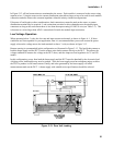
Input connections are made to the + and − connectors on the back of each module. A major consideration in
making input connections is the wire size. The minimum wire size required to prevent overheating may not be
large enough to maintain good regulation. It is recommended that stranded, copper wires be used. The wires
should be large enough to limit the voltage drop to no more than 0.5 V per lead. Table 3-3 gives the maximum
load lead length to limit the voltage drop to the specified limit.