


Section2: Assembly
iMPORTANT: Checkgear oii ievet in both
transmissions after the first 2 hours of
new tiiier operation, then every 30
operating hours thereafter. SeeSection 5
for instructions.
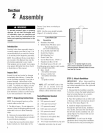
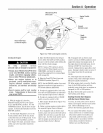
Figure 2=12: Checking oil level on
Power Unit Transmission.
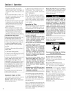
Figure 2o13: Checking oil level on
Tine Attachment Transmission.
STEP 7: Add Motor Oil to Engine
1. Beforeadding motor oii, park thetiller
oil ieveiground. Levelthe engine by
placing asturdy block under thetines or
the tines depth regulator bar.
2. Referto the EngineOwner's ManuaI
provided with your tiiier for detaiiedinfor-
mation on how to add motor oil andfor
motor oil specifications.
IMPORTANT:Two 20 oz. bottles of motor
oii are included with your tiiier. Checkthe
oii ievei as instructed in the Engine
Owner's Manual provided with your tiiier
BEFOREpouring the full amount of each
bottle into the engine.
iMPORTANT:
° Changeengine oil after first 2 hours of
new operation.
. Checkengine oii ieve! every 5 hours of
operation or each use.
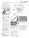
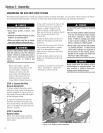
STEP 8: Attach Engiee Throttle
Lever and Cable
Forshipping purposes,the throttie cabie,
together with the throttie iever, is wound
around the engine. Carefuiiyunwind the
cable. If the throttle controi iabetis
covered with a clearprotective coating,
peel it off.
To avoid electric shock from a short
circait (electric start tiJJers only), never
allow the throttle cabte to roach the
battery. Route cabte below the battery,
on the outside of the batteryholder.
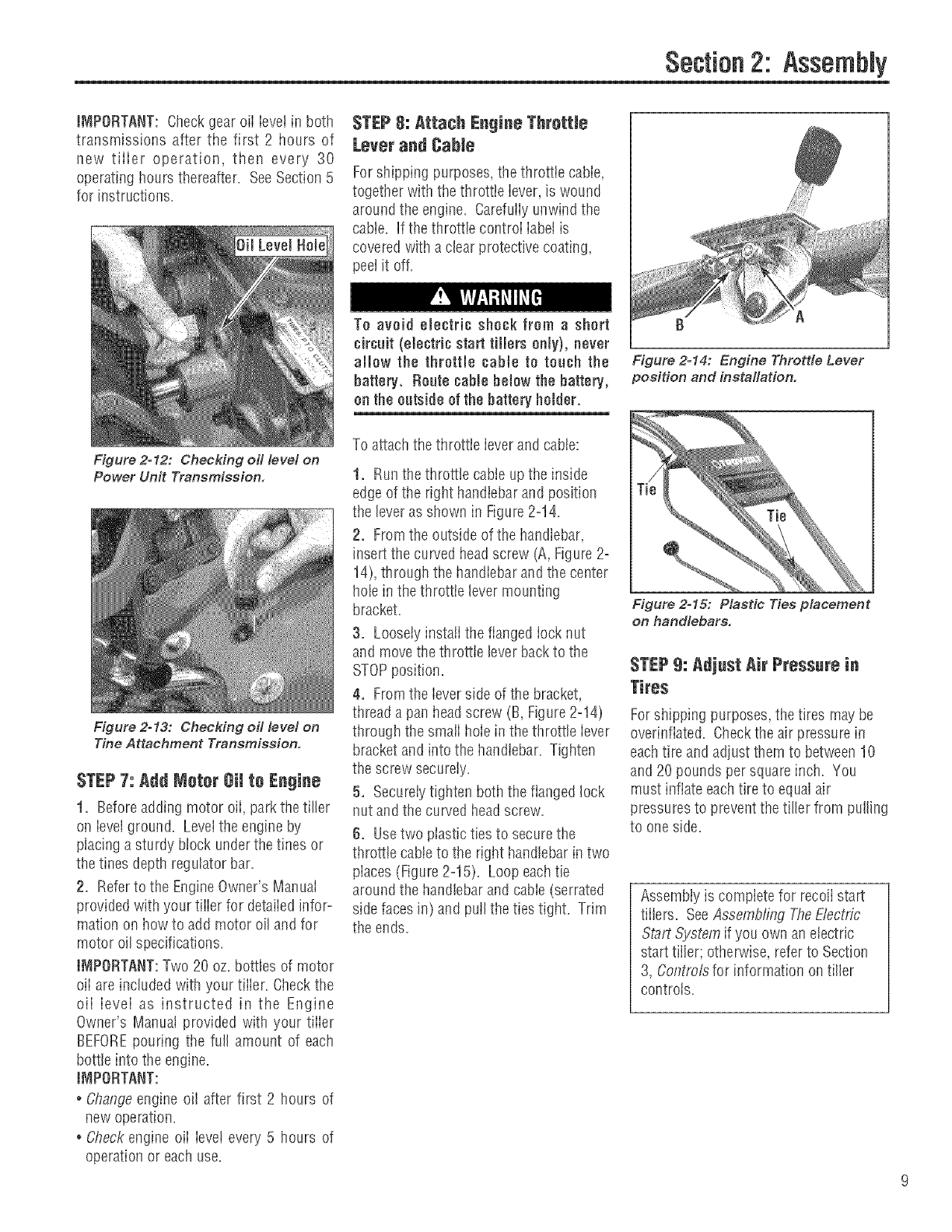
To attachthethrottle leverand cable:
1. Runthe throttle cableup the inside
edge of the right handlebarand position
the leveras shown in Figure2=14.
2. Fromthe outside of the handlebar,
insert the curved headscrew (A,Figure2=
14),through the handlebarand the center
hole in thethrottie levermounting
bracket.
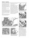
3. Loosely instaii the flanged iock nut
and movethe throttle leverback to the
STOPposition.
4. Fromthe leverside of the bracket,
thread a pall headscrew (B, Figure2=14)
through the smaii hoie in thethrottle iever
bracket and into the handlebar. Tighten
the screw securely.
5. Secureiytighten both theflanged lock
nut and the curved head screw.
6. Usetwo plastic ties to securethe
throttle cableto the right handlebar intwo
places (Figure2=15). Loop eachtie
around the handlebar and cable(serrated
side facesin) and pulIthe ties tight. Trim
the ends.
f} A
Figure 2-14: Engine Throttle Lever
position and installation.
Figure 2o15: Plastic Ties placement
on handlebars.
STEP9: Adjust Air Pressurein
Tires
Forshipping purposes,the tires may be
overinflated. Checkthe air pressure in
eachtire and adjust them to between10
and 20 pounds per squareinch. You
must inflate eachtire to equalair
pressuresto prevent thetiller from pulling
to one side.
Assembiy is compiete for recoiistart
tiilers. SeeAssembling TheElectric
Start System if you own an electric
start tiller; otherwise, refer to Section
3, Controlsfor information oil tiller
controls.