


Section4: Operation
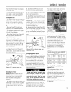
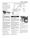
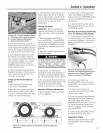
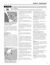
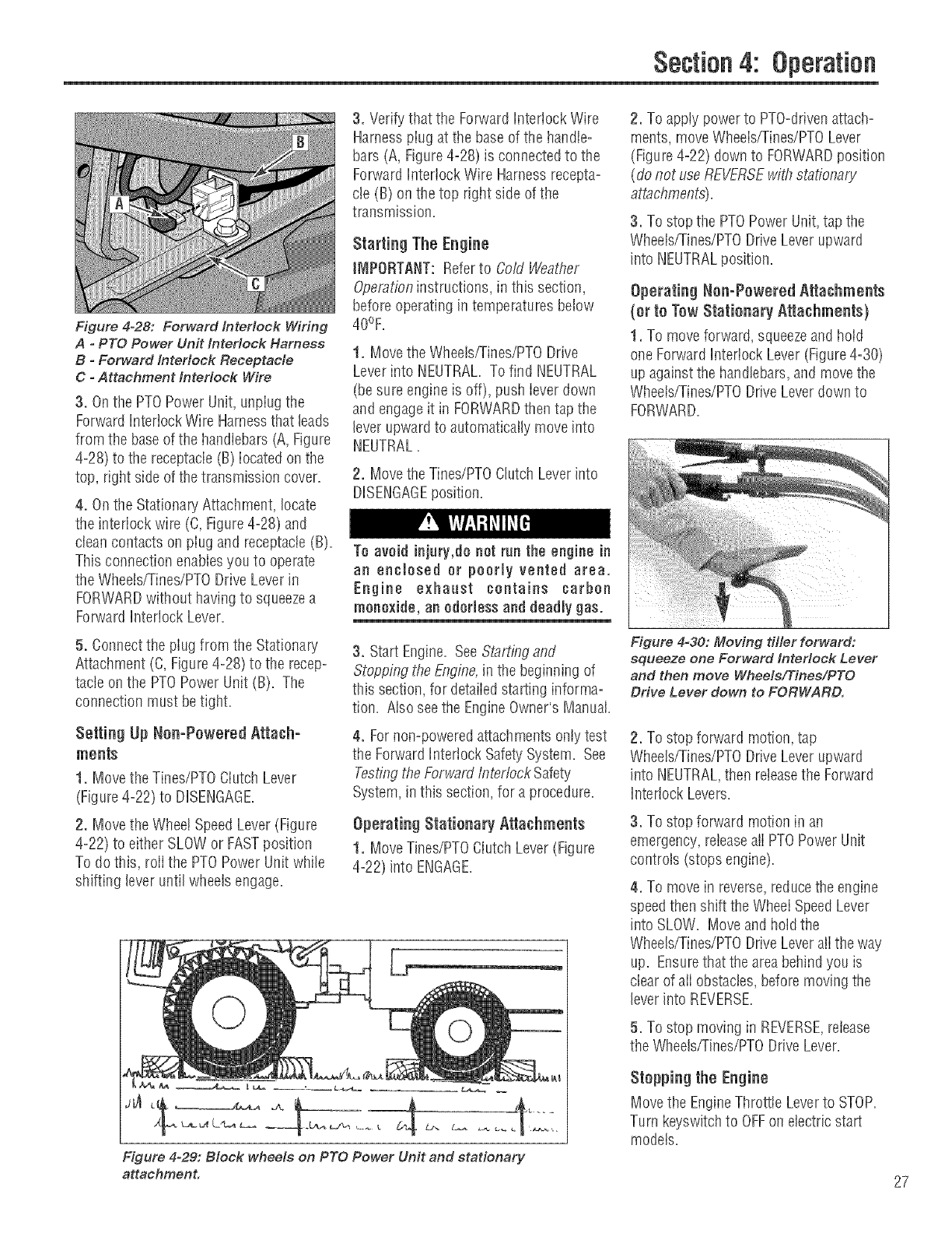
Figure 4-28: Forward tntedock Wiring
A - PTO Power Unit interlock Harness
B ° Forward Interlock Receptacle
C °Attachment lnteHock Wire
3. Onthe PTOPower Unit,unpIugthe
ForwardInterlock Wire Harnessthat leads
from the baseofthe handlebars(A,Figure
4-28) to the receptacle(B) located on the
top, right side ofthe transmission cover.
4. Onthe StationaryAttachment, locate
the interiock wire (C, Figure4-28) and
cleancontacts on plug and receptacle(B).
This connection enablesyou to operate
the Wheets/Tines/PTODrive Leverin
FORWARDwithout havingto squeezea
ForwardInterlock Lever.
5. Connectthe plug from the Stationary
Attachment (C, Figure4-28) to the recep-
tacle on the PTOPower Unit (B). The
connection must betight.
Setting Up Nee-Powered Attach-
ments
1. Move theTines/PTOClutch Lever
(Figure4-22) to DISENGAGE
2. Move the WheelSpeedLever(Figure
4-22) to either SLOWor FASTposition
To do this, rolithe PTOPower Unit while
shifting lever until wheels engage.
3. Verify that the Forward Interlock Wire
Harnessplug atthe baseof the handle-
bars (A, Figure4-28) is connectedto the
ForwardInterlock Wire Harnessrecepta-
cle (B) on thetop right side ofthe
transmission.
Starting The Engine
iMPORTANT: Referto Co/d Weattier
Operationinstructions, in this section,
before operating in temperatures below
40%=
1. Movethe Wheels/Tines/PTODrive
Leverinto NEUTRAL.To find NEUTRAL
(besure engine is off), push ieverdown
and engageit in FORWARDthen tapthe
lever upwardto automaticallymove into
NEUTRAL,
2. MovetheTines/PTOClutch Leverinto
To avoid injury,do not run the engine in
an enclosed or poorly vented area.
Engine exhaast contains carbon
monoxide, an odorless and deadly gas.
3. Start Engine. SeeSta/ting and
StoppflTgthe Engine,in the beginning of
this section, for detaiiedstarting informa-
tion. Atso seethe EngineOwner's Manual.
4. Fornon-poweredattachments onlytest
the ForwardInterlock SafetySystem. See
TestingtheForward flTtertockSafety
System,in this section, for a procedure.
Operating Statinnar_] Attachments
1. MoveTines/PTOClutchLever(Figure
4-22) into ENGAGE.
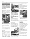
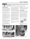
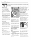
Figure 4-29: Block wheels on PTO Power Unit and stationary
attachment.
2. To applypowerto PTO-drivenattach-
ments, moveWheeis/Tines/PTOLever
(Figure4-22) down to FORWARDposition
(do not useREVERSEwit!",,stationary
attachments).
3. To stop the PTOPowerUnit,tap the
Wheels/Tines/PTODriveLeverupward
into NEUTRALposition.
Operating Nen-Pnwered Attachments
(or tn Tow Statinnary Attachments)
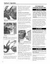
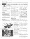
1. To move forward, squeezeand how
one ForwardInteriock Lever(Figure4-30)
up againstthe handlebars,and movethe
Wheeis/Tines/PTODriveLeverdownto
FORWARD.
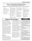
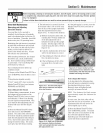
Figure 4-30: Moving drier forward:
squeeze one Forward tntedoek Lever
and then move Wheels/Tines/PTO
Drive Lever down to FORWARD.
2. To stop forward motion, tap
Wheels/Tines/PTODriveLeverupward
into NEUTRALthen releasethe Forward
Interlock Levers.
3. To stop forward motion in an
emergency, releaseaII PTOPowerUnit
controls (stops engine).
4. To move in reverse,reducethe engine
speedthenshift theWheelSpeedLever
into SLOW. Moveand hold the
Wheelsfrines/PTO DriveLeverali theway
up. Ensurethatthe areabehindyou is
clear of aii obstacles,beforemoving the
leverinto REVERSE.
5. To stop moving in REVERSE,release
the Wheels/Tines/PTODrive Lever.
Stepping the Engine
Movethe EngineThrottle Leverto STOP.
Turn keyswitchto OFFon electricstart
models.
27