


Section
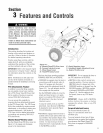
3 =ea u
Before operating your machine,
¢arefuJJy read and understand aJJ
safety, controls, operating instructions
in this Manual, the separate Engine
Owner's Manual and on the decals on
the machine.
Failure to fellow these instructionscan
result in seriuus persunalinjury.
/F
Jntreduetion
This section describesthe location and
function of the controls andfeatures on
your tiiier. Referto Section 4, Operation
for detaiiedoperating instructions.
Practiceusingthese controis, with the
engine shut off, untiiyou completely
understandthe operation ofthe controls
and feelconfident with eachof them.
iMPORTANT:Referto the separateengine
manufacturer's Engine Owner's Manuai
for information about the controls on the
engine.
NOTE:Aii referencesto ieft,right, front
and rearof the machineare basedona
position behindthe handiebarsandfacing
forward.
PTO Attachments Feature
In addition to powerful tiiiing capabiiity,
you canquickly convert your machine
into a PTO(PowerTake=Off)PowerUnit
that is capableof towing or powering
various TROY-BILTattachments,
You canaccessthis capabiiity by
removing the tines attachment (powered
bythe PTOPower Unit). The PTOPower
Unit isthen avaiiabtefor engine powered
attachments,or for puiiing or towing non-
poweredattachments. SeeSection 4,
PTOPower Unitfor detaiiedinformation
on instaiiing and operatingTROY-BILT
PTOattachments.
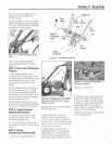
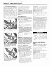
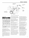
Wheelo/TiueoiPTODrive Lever
Usethe VVheets/Tines/PTODrive Lever (A,
Figure3-1) to engageand disengage
powerto thetransmission.
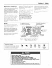
Figure 3-1:
A= Whee/s/Tinee/PTO Drive Lever
B= Forward Interlock Levers
C= Wheel Speed Lever
D= Tines/PTO Clutch Lever
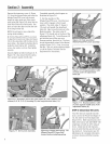
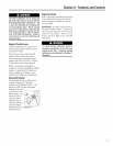
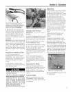
This lever hasthree operatingpositions:
FORWARD,NEUTRALand REVERSE.
,, FORWARDis engagedwhenthe leveris
moved down untilthe clutch roller (G,
Figure3-2) engagesinto the detent
position under the adjustment block (H,
Figure3-2). You wilI definitely feelthe
leverengageinto this position.
Usethe FORWARDsettingto movethe
wheels andtines forward, or to apply
power to an optional PTO(PowerTake
Off) attachment. (Seealso Forward
Interlock Levers.)
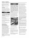
To stop the wheeis,tines or any PTO
attachment,movetheIeverto NEUTRAL
by tapping the iever upwards (Figure
3=3)and releasing.
REVERSEis engagedwhenthe lever is
pushed (with an open palm) aii the way
up and heid in that position (Figure3-4).
Usethis setting to movethe wheetsin
reverse. To stop moving in reverse,
reteasethe lever; it automatically returns
to the NEUTRALposition.
E= Depth Regulator Lever
F= Handlebar Height Adjustment Lever
G= Engine Throtde Lever
JNIPOflTANT: Do not operatethe tines or
any PTOattachment in REVERSE.
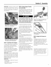
NEUTRAListhis control's normai non-
operating position. Theiever returns to
NEUTRALwhenit is tappedout of the
FORWARDposition or releasedfrom the
REVERSEposition. NEUTRALposition
is betweenFORWARDand REVERSE
(Figure3-3). Usethis setting to stop
the wheels,tines or any PTOattach-
ment.
IMPORTANT: Always shift to NEUTRAL
before starting the engine or before
engaging the wheels, tines or any PTO
attachment.
Forward interlock Levers
The Forward h_ter!ockLevers(B,
Figure3-1) areattached undereach
handlebargrip.
You must squeezeat ieast one of these
interlock ievers up against the handlebar
grip wheneverthe Wheets/Tines/PTO
Drive Leveris engagedin FORWARD
position.
11