


Section4: Operation
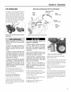
PTOPOWERUNiT
Your tiller is a self-contained PTO(Power
Take-Off) PowerUnit that was shipped
with a tine attachment instaliod. Thetine
attachment canbe quickly removedand
ropiacedwith other optionalattachments.
Thefoliowing instructions wili famiiiadze
you with your PTOPower Unit. Please
readthese pagescarefully.
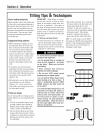
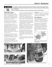
Removing And Replacing The Tine Attachment
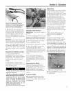
Figure 4-21: PTO Power Unit and tine
attachment.
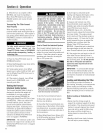
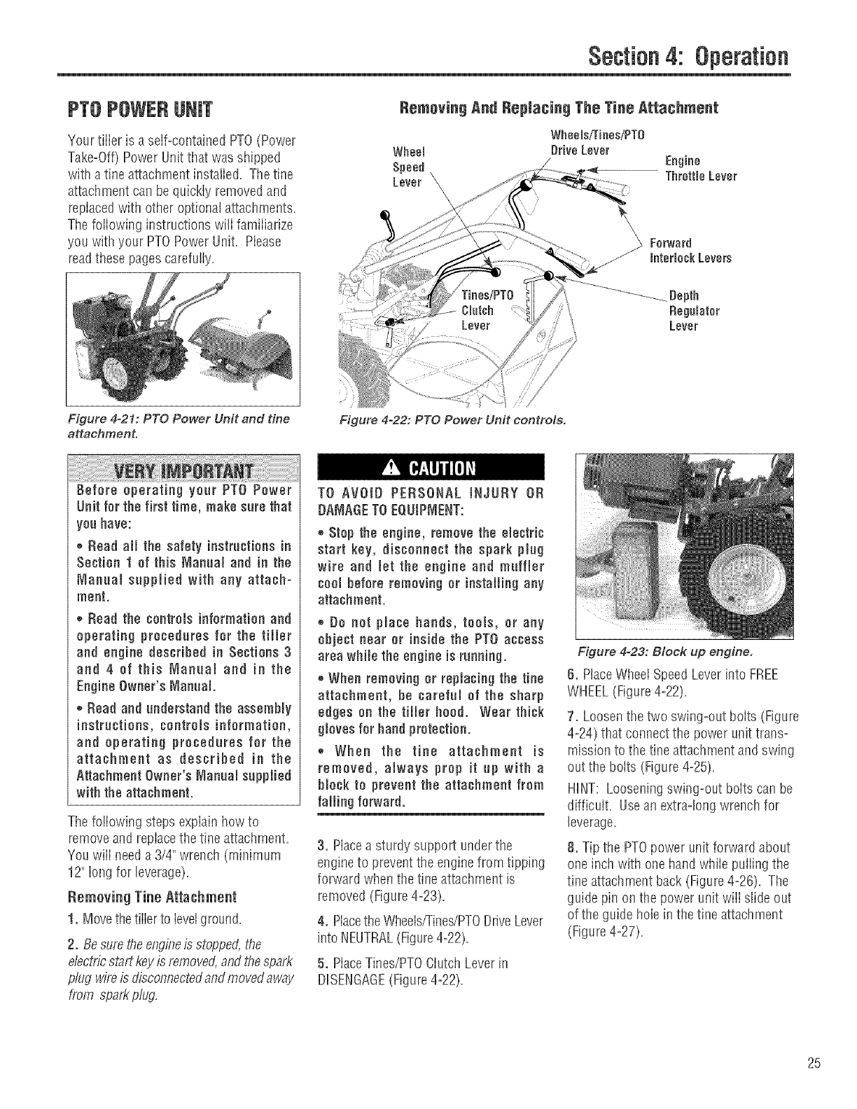
Figure 4-22: PTO Power Unit controls.
Before operating year PTO Power
Unit for the first time, make sure that
you have:
,_Read all the safety instructionsin
Section 1 of this Manual and in the
Manual supplied with any attach-
mont.
® Road the contromsinformation and
operating procedures for the tiller
and engine described in Sections 3
and 4 of this Manual and in the
EngMeOwner's Manual.
®Road and understand the assembly
instructions, controls information,
and operating procedures for the
attachment as described in the
Attachment Owner's ManaaJ suppmied
with the attachment.
Thefo!iowing stepsexplain howto
removeand replacethe tine attachment.
You will needa 3/4" wrench (minimum
12" Iongfor leverage).
Removing Tine Attachment
1. Movethetiiier to ievotground.
2. Besu/e theengineisstopped,the
e/ect//cstair keyis/emoved,and thespa/t
p/ug wifeis disconnectedandmovedaway
from sparkp/ug.
TO AVOID PERSONAL INJURY OR
DAMAGE TO EQUIPMENT:
® Stoptheengine,removetheomectric
start key, disconnect the spark plug
wire and Jotthe engine and muffJor
teembeforeremovingor MstaHMg any
attachment.
,, Do not place hands, teeM, or any
objectnearor Msido thePTO access
area whim the ongMe is running.
®When removing or roplacMg the tine
attachment, be careful of the sharp
edges on thetiIMrhood. Wear thick
gloves for handprotection.
® When the tino attachment io
removed, always prop it up with a
hMck topreventtheattachmentfrom
faJJingforward.
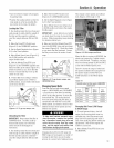
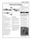
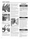
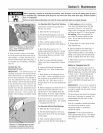
3. Placea sturdy support underthe
engineto prevent the enginefrom tipping
forward when thetine attachment is
removed (Figure4-23).
4. PIacetheWhools/Tines/PTODriveLever
into NEUTRAL(Figure4-22).
5. PlaceTines/PTOClutch Leverin
DHSENGAGE(Figure4-22).
Figure 4-23: Block up engine.
6. PlaceWheelSpeedLeverinto FREE
WHEEL(Figure4-22).
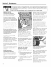
7. Loosenthe two swing-out boits (Figure
4-24) that connectthe power unit trans-
mission to the tine attachmentand swing
outthe boits (Figure4-25).
HINT: Looseningswing-out boits canbe
difficult, Usean extra-long wrench for
leverage,
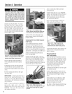
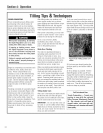
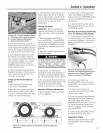
8. Tip the PTOpower unit forward about
one inchwith one hand whiio puliing the
tine attachment back (Figure 4-26). The
guide pin on the power unit wiii slide out
of theguide hole in the tine attachment
(Figure4-27).
25