


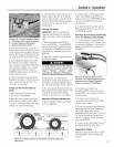
Section5:
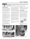
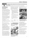
Figure 5=19: Move top half of belt
over pulley and reverse disc.
Figure 5=20: Shift into FORWARD
and remove the belt.
Figure 5=21: Seat belt in upper
pulley, then in lower pulley (High
Range position shown).
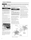
Reverse Disc inspection
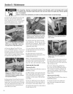
The reversedisc is madeof steel with a
speciai, iong=iastingrubber compound
bondedto the disc rim= Sincethis is a
wearing part, it shoutd be inspectedafter
every 30 operatinghours=
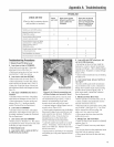
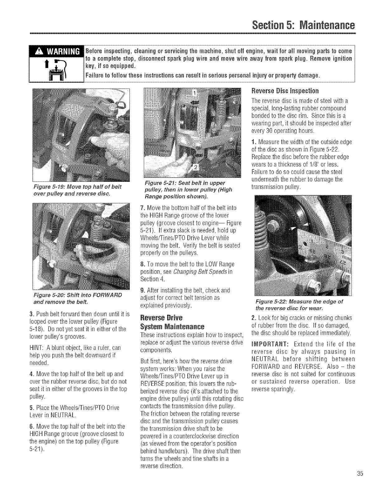
1. Measurethe width ofthe outside edge
ofthe disc as shown in Figure5=2£
RepIacethe disc beforethe rubber edge
wears to a thickness of 1/8"or iess.
Failureto do so could causethe steel
underneaththe rubber to damagethe
transmission pulley=
7. Move the bottom half ofthe belt into
the HIGHRangegroove ofthe lower
puliey (groove closest to engine-- Figure
5=21). If extra slack is needed,hold up
Wheels/Tines/PTODrive Leverwhile
moving the belt. Verify the belt is seated
properiy on the pulieys.
8. To movethe beltto the LOWRange
position, seeChangingBeltSpeedsin
Section 4.
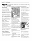
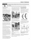
3. Pushbelt forward then down until it is
looped overthe lower pulley (Figure
5=18). Donot yet seat it in either of the
lower pulley's grooves.
HINT: A blunt object, Iike a ruler, can
help you push the belt downward if
needed.
4. Move thetop hair of the bett up and
overthe rubber reversedisc, but do not
seat it in either ofthe grooves in the top
pulley.
5. Piacethe Wheels/Tines/PTODrive
Leverin NEUTRAL.
6. Move thetop half of the belt into the
HIGHRangegroove (groove closest to
the engine) on thetop pulley (Figure
5-21).
9. After instaliing the belt, check and
adjust for correct belttension as
explainedpreviously.
Reverse Drive
System Maintenance
Theseinstructions expiainhow to inspect,
reptaceor adjust the various reversedrive
components.
Butfirst, here'show the reversedrive
system works: Whenyou raisethe
Wheeb/Tines/PTODrive Leverup in
REVERSEposition, this iowers the rub°
berizedreverse disc (it's attachedto the
engine drive puiiey) untii this rotating disc
contactsthe transmission drive puiiey.
Thefriction betweenthe rotating reverse
disc and the transmission puiiey causes
thetransmission driveshaft to be
powered in a counterciockwise direction
(asviewedfrom the operator's position
behind handlebars)=The driveshaft then
turns the wheelsand tine shafts in a
reversedirection.
Figure 5-22: Measure the edge of
the reverse disc for wear.
2. Lookfor big cracks or missing chunks
of rubber from the disc. If so damaged,
the disc should be repiacedimmediately.
tI_IPORTANT: Extend theIife of the
reverse disc by always pausing in
NEUTRAL before shifting between
FORWARD and REVERSE. Also-the
reverse disc is not suited for continuous
or sustained reverse operation. Use
reversespanngiy.
35