


Section
To preventpersonal injury or property
damage, do not start the engine until
aJJ assembly steps are complete and
you have read and understand the
safety and operatinginstructionsin this
manual
introduction
Carefuiiyfoiiow these assembiy stepsto
correctly prepareyour tiiier for use. It is
recommendedthat you readthis Section
in its entirety beforebeginning assembly.
NOTE:Threedifferent Horse model tiiiers
are covered in this Manual.Use oniythe
information applicableto your model.
Tiiier enginesvary by model.Your engine
mayappear differently than those found
in illustrations of this manual.
inspect Unit
h_spectthe unit and carton for damage
immediately after deiivery. Contactthe
carrier (trucking company) if you find or
suspect damage. Inform them ofthe
damageand request instructions for fiiing
a claim. To protect your rights, putyour
ciaim in writing and maiIa copy to the
carrier within 15 days after the unit has
been delivered.Contact us atthe Factory
if you needassistancein this matter.
STEP 1: Unpacking instructions
NOTE:Donot severelybend any ofthe
control cableson the unit.
1. Thetiiier is heavy. Donot attempt to
removeit from tire shipping piatform until
instructed to do so in these Assembly
steps.
2. RemoveaiI ueassembtedparts from
the carton. Thehardwarebag is included
in your literature packaging.
3. Checkthat you havethe items iisted
below (contact your local dealeror the
Factoryif anyitems are missing or
damaged).
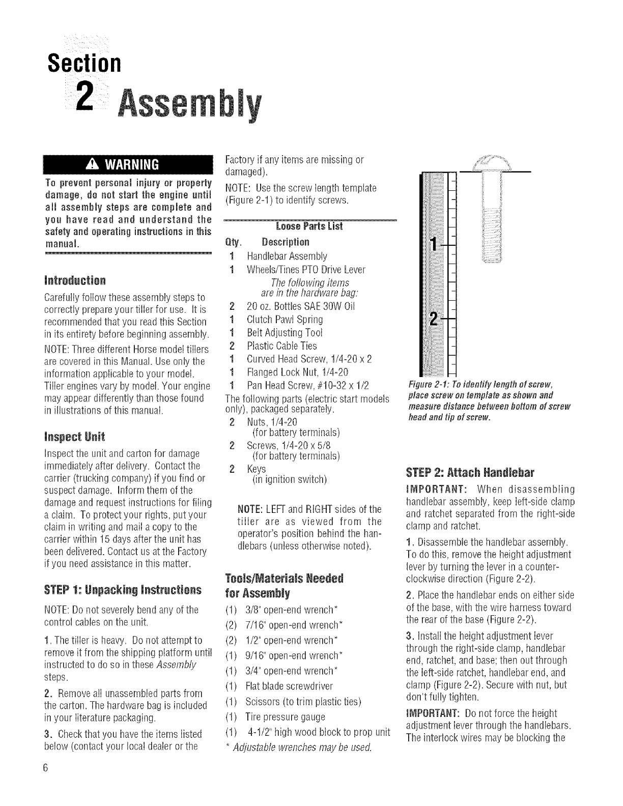
NOTE: Usethe screw iengthtemplate
(Figure2-1) to identify screws.
LoosePartsList
Qty. Bescription
1 HandlebarAssembly
1 Wheels/TinesPTODrive Lever
Thefor'towingitems
are in thehardwarebag:
2 20 oz. BotttesSAE30W Oil
1 Clutch PawiSpring
1 BeltAdjusting TooI
2 PiasticCabieTies
1 Curved HeadScrew, 1/4-20 x 2
1 FlangedLock Nut, 1/4-20
1 PanHeadScrew,#10-32 x 1/2
The following parts (electric start models
only), packagedseparately.
2 Nuts,1/4-20
(for batteryterminals)
2 Screws, 1/4-20x5/8
(for batteryterminals)
2 Keys
(in ignition switch)
NOTE:LEFTand RIGHTsides of the
tiller are as viewed from the
operator's position behind the han=
dlebars (unless otherwise noted).
Toels/MateriaJs Needed
for Assembly
(1) 3/8" open-endwrench*
(2) 7/16" open-endwrench*
(2) 1/2" open-endwrench*
(1) 9/16" open-endwrench*
(1) 3/4" open-endwrench*
(1) Fiatblade screwdriver
(1) Scissors (to trim plastic ties)
(1) Tire pressure gauge
(1) 4-1/2" high wood block to prop unit
* Adjustable wrenchesmay be used.
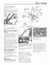
Fi lure 2-1: Toidentify lengthof screw,
place screw on template as shown and
measure distance between bottom of screw
head and tip of screw.
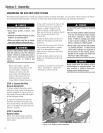
STEP 2: Attach Nandlebar
JNIPORTANT: When disassembling
handlebar assembly, keep ieft-side clamp
and ratchet separated from the right-side
clamp and ratchet.
1. Disassemblethe handlebarassembly.
To do this, removethe heightadjustment
leverbyturning the ieverin a counter-
clockwise direction (Figure2=2).
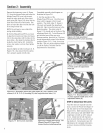
2. Placethe handlebarends on either side
ofthe base,with the wire harnesstoward
the rearof the base(Figure2-2).
3. Instalithe heightadjustment iever
through the rigirt-side clamp, handlebar
end, ratchet,and base;then out through
the left-side ratchet,handlebarend,and
clamp (Figure2=2).Securewith nut, but
don't fully tighten.
t_IPORTANT: Donot force the height
adjustment ieverthrough the handlebars.
The interlock wires may be blocking the