


Section2: Assembly
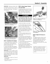
Removethe temporary screw (J,Figure
2=7)from the forward holes and move the
Wheelsffines/PTO Leverfuliy forward.
[nstalI the wider hook end of the dutch
pawt spring (M, Figure2=8)down into the
smaii hole atthe end of the handle. Use
piiers to insert the other end into the hole
in the long link bar (N).
NOTE:Donot bend or overstretch the
spring while instailing.
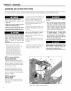
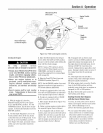
6. Pull the Wheets/Tines/PTOLeverback
to align the forward most holes (O,Figure
2=9)in the yoke plate with the holesin the
lever plates. Also align the bushing that is
insidethe short link bar (P). [nstalI the
screw, star washer, and nut, then tighten
securely.
Securelytighten all other hardware (Q,R,
Figure2=9). Also ensurethat the spring
(S) is properly seatedat both ends.
Completedassembly should appearas
illustrated in Figure2-9.
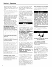
7. Testthe operation of the
Wheets/Tines/PTOLever. Pushthe iever
down until it engagesinthe Forward
position. The clutch roller (T, Figure2o
10) must rest beneaththe adjustment
block (U). Next, movethe iever up to the
Neutral position. The clutch rolier (T,
Figure2=11)shouid rest on the faceof the
adjustment block (U). To test Reverse,iift
and hoid the ieveraii the way up in
Reverseposition, then iet it go. Thelever
should automaticaliy return to the Neutrai
position (Figure2=11). If not, do not use
the tiiier. Seeyour local authorized dealer
or carlthe FactoryTechnicalService
Departmentfor instructions.
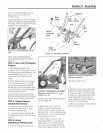
Figure 2-9: Fully assembled
Wheels/Tines/PTO Lever assembly.
Figure 2=10 Forward position; roller
(7")rests under the adjustment
block (U).
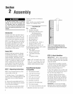
Figure 2=6: Illustration shows the yoke plates (H), nuts, washers, and
screws (A, E, B, F, D, G), bushing (C), and long and short finks (t, J).
Figure 2=7: Drive Lever assembly.
Figure 2=8: Clutch pawl spring. Tilt
WheelslTineslPTO Lever fully
forward before installing spring.
Figure 2=11: Neutral position; rofler
(T) rests against middle area of the
adjustment block (U).
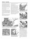
STEP6: CheckGearOil Levels
'four tiller hastwo separatetransmis=
sions: one for the PowerUnit (Figure2-
12), the other for the TineAttachment
(Figure2-13). Bothtransmissions were
fiiied atthe factory with SAE#85W-140
weight gear oil (with an A.PJ rating of
GU4). Check ieveIin both transmis-
sions to verify that they are stiii correct.
SeeSection5, TransmissionGearOff
MaflTtenancefor compiete information
on howto checkand fill the transmiso
sions.