


Section2: Assembly
leverand could bedamaged.You may
gentiy movethe wires asideif this
condition occurs.
4. Raisehandlebarsto one of two height
settings andtiglrten the height adjustment
lever. Also, makesureali other mounting
hardware issecurelytightened.
Left-Side
Clamp
and Nat
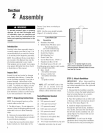
Figure 2=3. Fully assembled handle-
bars.
NOTE:Fully assembledhandlebar
assembly should appearas shown in
Figure2=3.
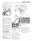
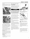
STEP 3: Meve Tiller Off Shipping
Piatferm
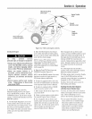
1. Setthe DepthRegulator Lever
(A, Figure2=4)to Travel position. Dothis
by lifting the tiiier bythe handiebars,then
puiiing straight back on the ievm and
siiding down to the highest notched
setting.
2. Setthe WheetSpeed Lever(B, Figure
2=4)to Freewheelposition. To do this,
movethe ieverapproximately halfway
betweenthe Fastand Siow settings whiie
you rockthe tiiim forward and backward
untilthe wheeis movefreely.
3. Lift Handlebarshigh enough to ciear
tiiier tines and pull back firmty to dislodge
the tiller from the platform wheel wells.
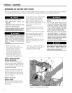
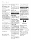
STEP 4: Cenneet Ferward
interlock Wire Harness
1. Removeany dirt from the Forward
Interlock wire harness plug (C, Figure
2=5)and its receptacle(D).
2. Connectthe ForwardIntmiock wire
harness plug (C, Figure2=5)to the recepo
tacle (D).
STEP 5: Attach
Wheels/Tines/PT8 Drive Lever
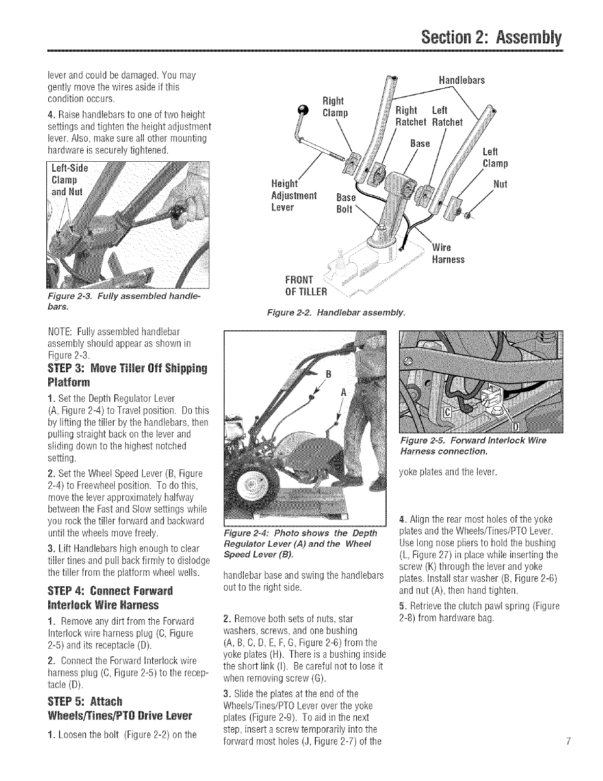
Right
Clamp
Left
Clamp
Nat
FRONT
OFTILLER
Figure 2-2. Handlebar assembly.
Wire
Harness
Figure 2=& Forward Interlock Wire
Harness connection.
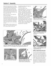
yoke plates and the lever.
Figure2-4: Photo shows the Depth
Regulator Lever (A) and the Wheel
Speed Lever (B).
handIebarbaseand swing the handlebars
out to the dglrt side.
2. Removeboth sets of nuts, star
washers, screws, and one bushing
(A, B,C, D, E,F,G,Figure2=6)from the
yoke piates (H). Thereis a bushing inside
the si_ortlink (i). Becarefui not to loseit
when removing screw (G).
3. Siide the ptatesat the end of the
Wheeis/Tines/PTOLeveroverthe yoke
plates (Figure2-9). To aid in the next
step, insert ascrew temporarily into the
forward most holes (J, Figure2=7)of the
4. Align the rear most holes of theyoke
platesand the Wheets/Tines/PTOLever.
Uselong nosepiiers to hold the bushing
(L, Figure27) in placewhile inserting the
screw (K) througtl the leverandyoke
plates.Install star wasller (B, Figure2=6)
and nut (A), then handtighten.
5. Retrievethe clutch pawl spring (Figure
2=8)from hardwarebag.
1. Loosenthe bolt (Figure2=2)on the 7