


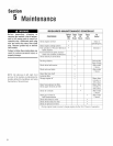
Section5: Maintenance
36
Before inspecting,deaning or servicing the machine, shut off engine, wait for all moving partsto came
to a cornpiete stop, disconnect spark plug wire and move wire away from spark plug. Remove ignition
key, if so equipped.
Failureto fellow these instructionscan result in serious personalinjury or propertydamage.
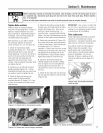
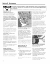
Replacing the Reverse Disc
Foilowthese stepsto repIacethe reverse
disc, (If your tiller hasa BumperAttach=
rnentmounted, it must be removedfirst=)
Removing the Reverse Disc
1. Move Wheets/rines/PTODrive Leverin
NEUTRALposition.
2. Wedgea 5/16"-thick board betweentop
of engine pulley (avoidcontacting reverse
disc) and cast iron housing next to it=
This immobilizes pulley=
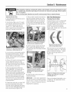
3. Usea 9/16" wrench to loosenthe
mounting bait shown in Figure5-23.
Rememberto irnrnobiiizethe pulieywith
the wood wedge whiie iooseningtire bolt.
If necessary,pry the disc from the puliey
with the tip of a screwdriver. Backthe
bait out asfar aspossible. Then angle
the disc a little to removeit. Bring the
bolt and Iockwasheralong with the disc.
Figure 5°23: Removing Reverse Disc.
/nstaltiflga New Reveme Disc
1. Dosteps 1=through-3,describedprevi-
ously, in reverse.
2. Tighten mounting bait securely, and
check for correct operation-- see
Checkingand Adjusting ReverseDrive
System=
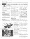
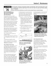
Checking and Adjusting
Reverse the Drive System
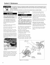
Whenthe Wheels/Tines/PTODrive Lever
is moved up into REVERSE,the engine
and engine mount move downto press
on the reverseadjustment bolt (Figure5-
24). Tills action compressesthe reverse
spring and plunger assembly, requiring
you to hoid ti_eiever up in REVERSE.
Whenyou reieasethe iever,the spring
autornaticatiypushes the leverback into
NEUTRALposition.
Thespring and piunger assembly is
designedto preventthe reversedisc from
making contact with the transmission
puliey until you shift into REVERSE.
Whenthe ieveris in NEUTRAL,the switch
body on the bottom of the engine mount
tab shouid be resting squareiy on top of
the reverseadjustment bolt (Figure5-24)=
The reverseadjustment bait canbe
adjusted up ordownto correct a number
of reversedrive operating probierns, as
explainednext.
Figure 5°24: Spring and plunger
assembly.
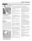
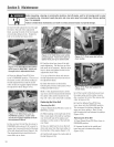
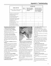
Checking and Adjusting Reverse Dhc
1. Verify'that iinkages for
Wheels/Tines/PTODrive Leverare Iubri-
cated with oii and engine mount barsand
bettadjustment block are iubricated with
grease= (See TillerLubrication in this
section=)
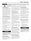
2. PlaceWheels/Tines/PTODrive Leverin
NEUTRAL=Briefly pulIout engine recoil
start rope whiie watching reversedisc.
The disc should turn, but iower puiiey
should not (Figure5-25)= If reversedisc
turns lower puliey, or if it is iocated c!oser
than 3/16" to the putley, reverseadjust-
merit bait should be adjusted upward (see
instructions that follow). Moving adjust-
rnent bolt upward wiii alsosolve problem
of a tiiler thatgoes into REVERSEon its
OWn,
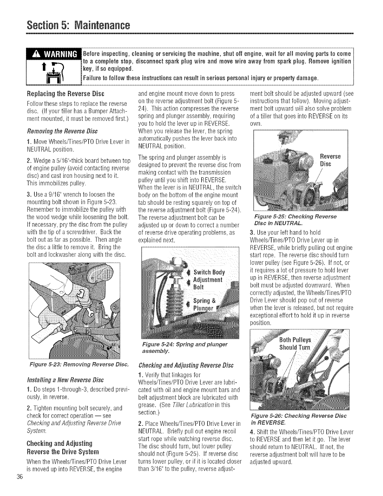
Figure 5-25: Checking Reverse
Disc in NEUTRAL.
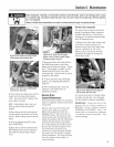
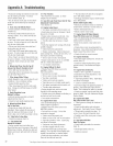
3. Useyour ieft hand to hold
Wheels/Tines/PTODrive Leverup in
REVERSE,while briefly pulling out engine
start rope=The reversedisc shoutd turn
lower putiey (seeFigure5-26)= If not, or
it requiresa iot of pressureto hoid iever
up in REVERSE,then reverseadjustment
bait must be adjusted downward. When
correctly adjusted,the Wheeis/Tines/PTO
Drive Levershould pop out of reverse
whenthe ieveris reieased,but not require
exceptionaleffort to hold it up in reverse
position.
Figure 5°26: Checking Reverse Disc
in REVERSE.
4. Shift the Wheetsfrines/PTODrive Lever
to REVERSEand then let it go. The lever
should returnto NEUTRAL. If not, the
reverseadjustment bolt will haveto be
adjusted upward.