


Section5: Maintenance
$terin9 Your Titler
Whenyour tiiier won't be usedduring the
off-season,prepareit fer storagewith the
following steps:
1. Cleanthe tiller andengine.
2. De routine tiiier iubricatien and check
for loose hardware.
3. Protectthe engine from deterioration
er damageby referring te the engine
storage instructions in your engine
manualiiterature=
4. Whenengine is still warm, drain eiI
from enginecrankcase. Refillwith fresh
motor oii.
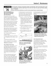
5. Protect internal cyiinder against rust by
removing spark plug and pouring ene
ounceef cleanengine oii into spark plug
hole. Thenstewiy puli out receiistart
rope 2 or 3 times te distribute eil inter-
natiy. Repiacespark plug, but do not
reconnectpiug wire. Puli rope untii resis-
tance is felt -- iet rope rewind.
5. Chargebattery (electric start option).
Storebattery in cool, dry location.
7. Move Wheels/Tines/PTODrive Leverte
NEUTRALposition. Keeptiller in a clean,
dry area.
8. Neverstore tiiier with rue!in fuel tank
in an enclosedarea where gasfumes
could reachair openflame or spark, er
where ignition sources are present (space
heaters,hot water heaters,furnaces,etc.).
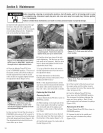
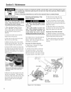
inspecting Ferward JnterJeck
Wiring System
Checkthe Ferward h_terieckwiring
systemevery ten (10) operating hours,
fer tight cennections andto seethat the
insulation en the wires is unbreken (te
preventthe system from sherting eut)=
1. Checkinsulated wire harnessfrom
lower endsof handlebarsto wire harness
connecter en tep, right sideof transmis-
sion cover= Besure connector is secure=
2, Checkinsulatedtubing from connecter
te cast iron motor mount/belt shroud.
3. Checkthe wire ieadingfrom thetubing
everto the switch assembly mounted on
tep ef the tab on the cast iron motor
mount-belt shroud. Also checkthe
secondwire that leadsto the throttle
cablemounting bracket onthe right side,
forward portion ofthe engine.
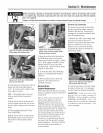
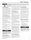
Testing the Ferward
Jnterleck Wiring System
The wiring circuit for the Forward
Interleck SafetySystemis designedto
ground eut theengine's ignition system.
Thereare threeswitches in the circuit
which, when open,ietthe engine run.
Oneswitch is en the neutral piunger tab
ef the castiron motor mount. This switch
is open wheneverthe WheelsYrines/PTO
Drive Leveris in NEUTRALor REVERSE
positions. Theother twe switches are
located insidethe handlebars,directly
abovethe twe Forward Interleck Levers.
Theswitches arewired sewhen squeezed
(open) the engine will run. Thereis a
fourth switch iocatedin the wiring
harnessconnector on thetop, right side
ef the transmission cover, it warns you if
theconnection is not mated by not ietting
theengine run while the Wheetsfrines/PTO
Drive Leveris in FORWARD=
1. A broken er disconnected wire ceuId
let the engine run witheut yeu havingto
press ene of the ForwardInterlock Levers.
2. A barewire touching tiiier er engine
metal could greund eut the engine's
ignition.
3. A switch that hasfaiiedaliows the
engineto run. Or it mayprevent the
enginefrom running.
Referto the Troubieshootingsection if
your ForwardInterieck Safety System is
net operating correctly.
4O