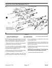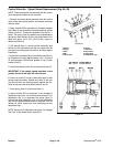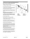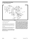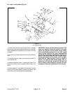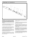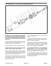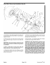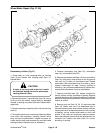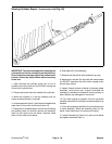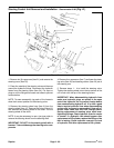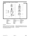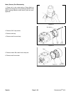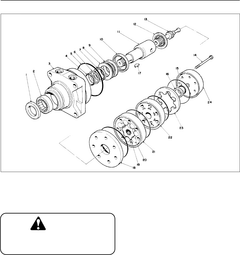
Wheel Motor Repair (Fig. 37, 38)
Figure 37
Disassembly of Motor (Fig. 37)
1. Place motor in a vise, clamping down on housing
(Item 3) port bosses with coupling shaft (Item 11)
pointed down.
If motor is not firmly held in the vise, it could
be dislodged during the service procedures,
causing personal injury.
2. Remove the seven (7) special bolts (Item 14) using a
9/16 inch thin wall socket. Inspect bolts for damaged
threads, or sealing ring under bolt head. Replace dam-
aged bolts.
3. Remove end cover assembly (Item 24) and seal ring
(Item 5).
4. Thoroughly wash cover in solvent and blow dry. Make
sure cover valve apertures, including internal orifice
plug, are free of contamination. Inspect end cover for
cracks and the bolt head recesses for good bolt head
sealing surfaces. Replace cover as necessary.
5. Remove commutator ring (Item 23), commutator
(Item 16), and manifold (Item 22).
6. Remove commutator seal (Item 15) from commutator
(Item 16), using an air hose to blow air into ring groove
until seal ring is lifted out and discard seal. Inspect
commutator and commutator ring for cracks or burrs.
Inspect commutator for wear, scoring, spalling or
brinelling. If any of these conditions exist, replace com-
mutator and commutator ring as a matched set.
7. Remove manifold (Item 22). Inspect manifold for
cracks, surface scoring, brinelling or spalling. Replace
manifold that shows any of these conditions. A polished
pattern on the ground surfaces from commutator or rotor
rotation is normal.
8. Remove rotor set (Item 19, 20, 21) and wear plate
(Item 18). Retain rotor set in its assembled form to
maintain the same rotor vane to stator contact surfaces.
Inspect rotor set in its assembled form for nicks, scoring,
or spalling, on any surface and broken or worn rotor
splines. If any rotor set component requires replace-
ment, the complete rotor set must be replaced as it is a
matched set. Inspect the wear plate for cracks,
brinelling, or scoring.
CAUTION
Greensmaster
®
3100 Page 4 - 55 Repairs


