


Greensmaster 3100
Dual Point Adjust Cutting Units
Page 10 - 20
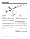
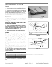
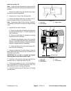
Front Roller Removal and Installation
Removal (Fig. 23)
1. Position machine on a clean and level surface, low-
er cutting units, stop engine, engage parking brake, and
remove key from the ignition switch.
Note: The front roller can be removed with the cutting
unit either attached to the lift arm or removed from the
lift arm. Determine your maintenance needs.
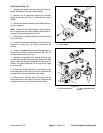
2. Loosen cap screws securing the roller shafts to
each front bracket.
3. Remove the lock nut, tab washer, and carriage
screw securing one of the front roller brackets to the cut-
ting unit frame assembly.
4. Remove the front bracket and slide the roller and
shaft from the cutting unit. Remove the remaining front
roller bracket if necessary.
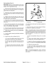
Installation (Fig. 23)
1. Place cutting unit on a level working surface.
2. If both front roller brackets were removed:
A. Insert carriage screw through the cutting unit
side plate and front bracket. Secure carriage screw
and roller bracket with tab washer and lock nut.
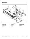
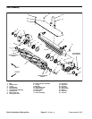
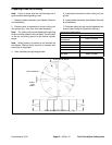
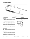
1. Cap screw
2. Roller assembly
3. Front roller bracket
4. Carriage screw
5. Lock nut
6. Tab washer
Figure 23
1
2
3
4
5
6
3. Slide roller shaft into the front bracket attached to
the cutting unit. Slide second front bracket on the other
end of roller. Secure bracket with carriage screw, tab
washer, and lock nut.
4. Apply Loctite 242 or equivalent to the cap screw
threads. Center roller in the front brackets and secure
into place with the cap screws.
5. Adjust cutting unit height–of–cut (see Cutting Unit
Operator’s Manual).
Rev. D