


Greensmaster 3100
Dual Point Adjust Cutting units
Page 10 - 11
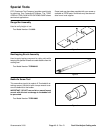
Bedbar Removal and Installation
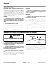
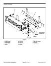
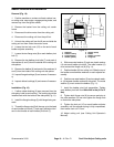
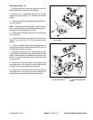
Removal (Fig. 10)
1. Position machine on a clean and level surface, low-
er cutting units, stop engine, engage parking brake, and
remove key from the ignition switch.
2. Remove the basket from the cutting unit carrier
frame.
3. Disconnect the drive motor from the cutting unit.
4. Disconnect the cutting unit from the pull link.
5. Unhook the cutting unit from the lift arm and slide the
cutting unit out from under the carrier frame.
6. Loosen the two lock nuts (15) on the end of each
bedbar adjuster assembly.
7. Loosen the two flange nuts (8) on each bedbar pivot
bolt (7).
8. Remove the two bedbar pivot bolts (7), and each of
the washers (4 and 5) from the outside of the cutting unit
side plates.
9. Remove the bedbar (6) and each of the washers (4
and 5) from the inside of the cutting unit side plates.
10. Inspect flange bushings (3) and remove if necessa-
ry.
11. Inspect rubber bushings (2) and remove if necessa-
ry.
Installation (Fig. 10)
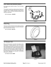
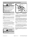
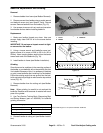
1. If either rubber bushing (2) was removed from the
side plate, install a new bushing. The bushing should be
installed flush with the inside of the side plate (Fig. 11).
2. Install the flange bushings (3) with flange facing out-
ward.
3. Thread the flange nuts (8) all the way up to the head
of each bedbar pivot bolt (7) and apply antiseize lubri-
cant to the threads of each bedbar pivot bolt (7).
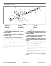
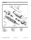
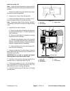
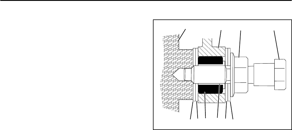
1. Sideplate
2. Rubber bushing
3. Flange bushing
4. Washer (plastic)
5. Washer (metal)
6. Bedbar
7. Bedbar pivot bolt
8. Flange nut
Figure 11
1
2345
678
54
4. Slide one metal washer (5) and one plastic washer
(4) onto each bedbar pivot bolt. The metal washer (5)
must contact the flange nut (8) (Fig. 11).
5. Position bedbar (6) into cutting unit. Slide the top of
the bedbar arms between washers on each adjuster as-
sembly.
6. Position one metal washer (5) and one plastic wash-
er (4) between bedbar and each side plate. The metal
washer (5) must contact the bedbar (Fig. 11).
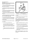
7. Install the bedbar pivot bolt assemblies. Tighten
each bedbar pivot bolt from 190 to 240 in–lbs (21 to 27
Nm).
8. Tighten both flange nuts (8) to remove end play at
the outer washers. Do not over tighten the flange nuts
or distort the side plates.
9. Tighten the lock nut (15) on each bedbar adjuster
assembly until the adjuster spring is fully compressed,
then loosen lock nut 1/2 turn.
10. Adjust cutting unit (see Cutting Unit Operator’s
Manual).
Rev. D