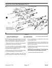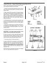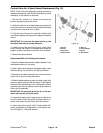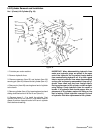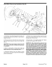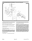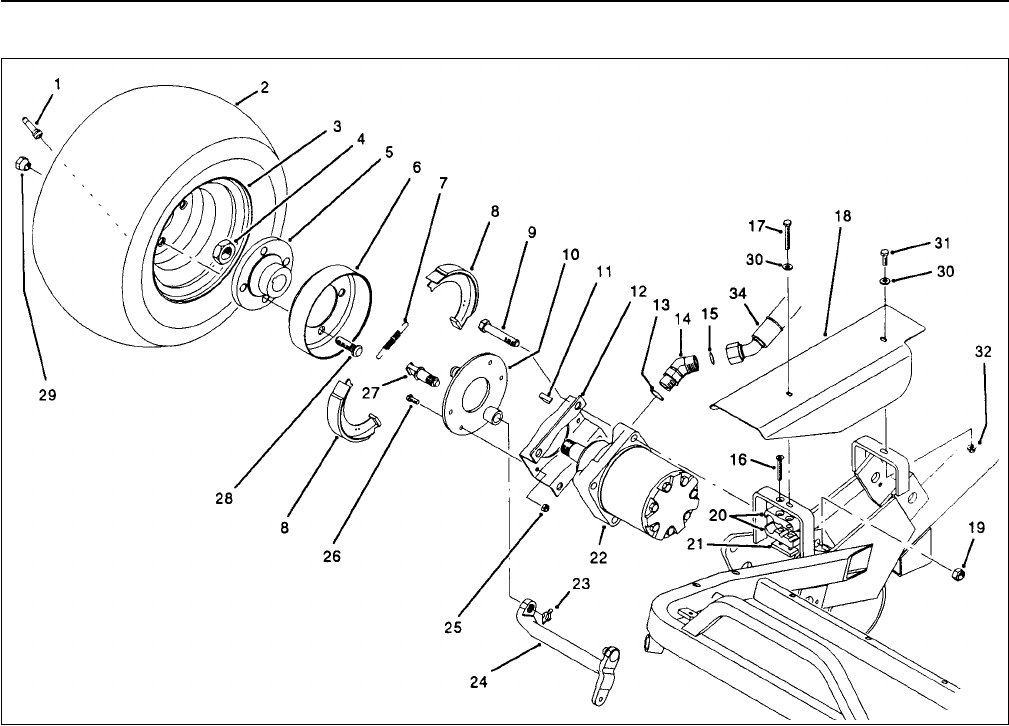
Wheel Motor Removal and Installation (Fig. 36)
Figure 36
1. Put blocks on each side off opposite drive wheel. Lift
the frame with a jack and use blocks or a jack stand to
support the frame.
2. Remove wheel nuts (Item 29) and remove wheel
(Item 3). Remove large nut (Item 4) from wheel hub
(Item 5).
IMPORTANT: To prevent damage to wheel motor, DO
NOT hit wheel hub with a hammer during removal
or installation.
3. Mount a wheel puller to wheel mount studs and
remove wheel hub (Item 5) and brake drum (Item 6).
Remove key (Item 11) from wheel motor shaft.
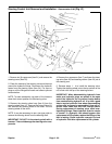
4. Disconnect hydraulic lines from fittings on wheel
motor (Item 22). Put caps on open lines and fittings to
prevent contamination.
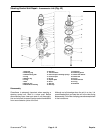
5. Remove four (4) capscrews (Item 9) and lock nuts
(Item 19) to remove wheel motor (Item 22) and brake
brackets (Item 12) from frame.
6. Reverse steps 1 - 6 to install the wheel motor. Tighten
nut (Item 4) to a torque of 250 - 400 ft-lb.
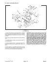
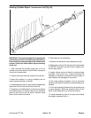
IMPORTANT: When disassembling hydraulic lines
make sure hydraulic plugs are placed in the open
end of the hydraulic line to prevent foreign debris
from contaminating hydraulic oil. It is also a good
idea to tag the hydraulic lines when disassembling
so they can be properly reassembled. Keep all hy-
draulic lines clean and free from foreign debris.
During replacement of wheel motor, avoid overtight-
ening fittings. Check hydraulic lines for cracks or
breaks. If a hydraulic leak should appear after re-
placement of lift cylinder, replace the fitting or line
that is leaking. Check hydraulic reservoir for level
of hydraulic fluid after replacement of lift cylinder.
Repairs Page 4 - 54 Greensmaster
®
3100


