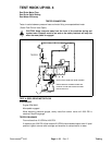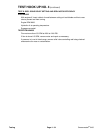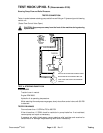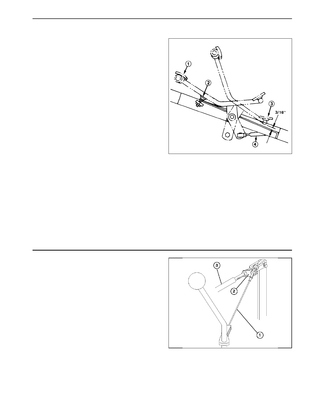
Traction Pedal Adjustment (Fig. 14)
To check forward and reverse operation of traction pedal
use the following procedure:
Reverse
1. Push down on rear of traction pedal (reverse) until
No. 5 section spool valve is completely pushed in.
2. Check distance between bottom of pedal and foot-
rest. Distance should be approximately 3/16 in. If dis-
tance is greater or less than 3/16 in. dimension, an
adjustment to the traction control rod is required.
3. Remove jamnut and balljoint securing control rod to
traction shaft pivot.
4. Loosen jamnuts securing balljoints to control rod and
adjust balljoints and control rod to get 3/16 in..
Forward
1. Push the traction pedal fully forward until No. 5
section valve spool is completely pulled out.
2. Pedal should contact pedal stop. If pedal contacts
stop before spool is completely out, or if pedal does not
make contact with stop, an adjustment to the stop is
necessary.
3. Loosen hex nut securing threaded rod to frame. Turn
flange nut on rod to raise or lower stop (rod), while
checking pedal.
4. When completed, retighten nut.
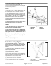
Figure 14
1. Fully forward 3. Reverse
2. Pedal stop 4. Control rod
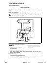
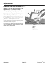
Traction Return Linkage (Fig. 14a)
If shift selector does not return to Neutral or No. 1
position from No. 2 position when mow pedal is en-
gaged, an adjustment to the traction return linkage is
required.
1. Loosen front jam nut securing cable assembly to
mow/lift control rod bracket.
2. Move shift lever to No. 1 position.
3. While holding mow/lift control rod in rear position,
tighten rear locknut to remove almost all slack from
cable assembly. Do not over-tension cable.
4. Tighten front jam nut ot lock adjustment.
5. Check operation and adjust again as necessary.
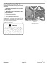
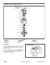
Figure 14a
1. Cable assembly 3. Mow/lift control rod
2. Mow/lift control rod bracket
Rev. B
Greensmaster
®
3100 Page 4 - 37 Adjustments


