


Maintenance
6–6
TDS3000 Series Service Manual
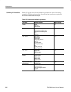
Table 6–2 lists the removal and installation procedures in order of increasing
complexity. Within each procedure, only perform the steps that are required to
access the modules that need repair.
Table 6–2: Removal and installation procedures
Procedure Modules accessed Begins on page
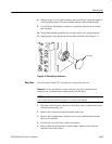
Handle Handle
Hub cover
Hub assembly
6–7
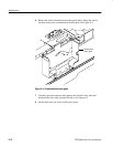
Rear case Rear case
Communication module cover
Communication module guide
Feet
Disk drive
6–11
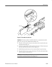
Rear chassis Rear chassis
Battery board
Power supply
Power supply bracket
Line filter
DC power cable
AC line power cable
Fan
Parallel printer port
External power jack
6–15
Main board Main board
Display cable
Disk drive cable
6–20
Front chassis and display
Module
Front chassis
Display module
Inverter cable
Inverter board
Display module
6–23
Display Inverter board
and backlights
Inverter board
Backlight tubes
6–26
Front panel Knobs
Front-panel board
Flex circuit keypad contacts
Keypads
6–31
Summary of Procedures