


Maintenance
TDS3000 Series Service Manual
6–39
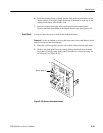
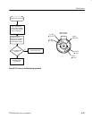
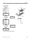
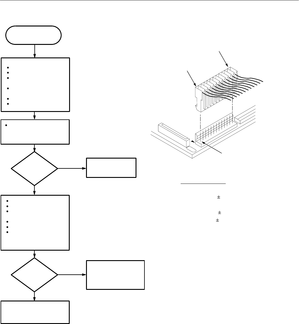
Measure voltages on
disconnected cable as shown in
diagram at right.
Power off oscilloscope.
Disconnect AC power cord.
Reconnect J100 cable to the
battery board.
Disconnect J900 cable from the
main board.
Connect AC power cord.
Power on oscilloscope.
Replace the Battery
board module.
No
Yes
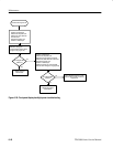
Are voltages within
tolerance?
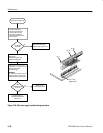
Power off oscilloscope.
Disconnect AC power cord.
Reconnect J900 cable to main
board.
Connect AC power cord.
Power on oscilloscope.
Measure voltages on
connected J900 cable as shown
in diagram at right.
Power distribution problem
on main board, front panel
board, or display. Proceed
to Figure 6–28.
No
Yes
Are voltages within
tolerance?
Power distribution OK. Proceed to
module isolation troubleshooting
(Figure 6–31).
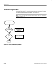
Continued from Figure 6–26.
Pin 1
Pin 1 J900
Main board
Connector DC Voltage
1 Gnd
2–4 5.1 V 0.15 V
5 Gnd
8 –15 V 1.2 V
9 15 V 1.2 V
10 Gnd
12 ~+5.5 V (disconnected)
~+3 V (connected)
Cable from
battery board
Pin 12
Figure 6–27: Battery module troubleshooting procedure