Maintenance
6–38
TDS3000 Series Service Manual
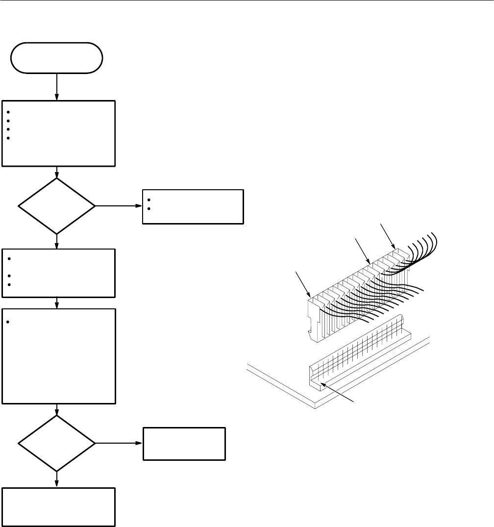
Reconnect loose cables.
Return to top of Figure 6–24.
No
Yes
Is there
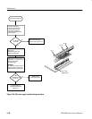
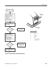
+15 volts between pins
13 and 18?
Measure for +15 V DC (± 0.5 V)
between line 13 (+) and line 18 (–) of
the disconnected cable.
(see figure at right)
!WARNING!
Be careful when measuring near the
AC power supply, as there are line
voltages present on exposed parts.
AC power supply OK.
Troubleshoot battery board
(Figure 6–27).
Continued from Figure 6–25.
Disconnect J100 cable from
battery board.
Connect AC power cord.
Power on oscilloscope.
Power off oscilloscope.
Disconnect AC power cord.
Remove instrument case.
Check that all cables are
connected and fully seated into
board connectors.
No
Yes
Are all cables
connected?
Replace the AC
Power Supply module.
Pin 13
Pin 18
Pin 1
Pin 1 J100
Battery board
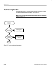
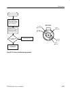
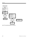
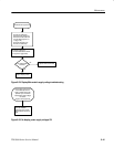
Figure 6–26: AC power supply troubleshooting procedure


