


Specifications
1–2
TDS3000 Series Service Manual
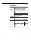
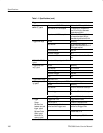
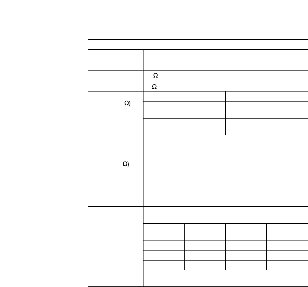
Table 1–1: Specifications (cont.)
Inputs
Input coupling DC, AC, or GND
Channel input remains terminated when using GND coupling.
Input impedance,
DC coupled
1 M ±1% in parallel with 13 pF ±2 pF, TekProbe compatible
50 ±1%; VSWR ≤ 1.5:1 from DC to 500 MHz, typical
Maxi
m
u
m
voltag
e
at
pNC1
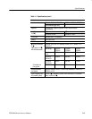
Overvoltage category Maximum voltage
in
p
ut B
NC
(
1
M
CAT I Environment (refer to
page 1–11)
150 V
RMS
(400 V
pk
)
CAT II Environment (refer to
page 1–11)
100 V
RMS
(400 V
pk
)
For steady-state sinusoidal waveforms, derate at 20 dB/decade above
200 kHz to 13 V
pk
at 3 MHz and above.
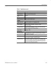
Maximum voltage at
input BNC (50
5 V
RMS
with peaks ≤ ±30 V
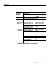
Maximum floating
voltage
0 V from chassis (BNC) ground to earth ground, or
30 V
RMS
(42 V
pk
) only under these conditions: no signal voltages
>30 V
RMS
(>42 V
pk
), all common leads connected to the same voltage,
no grounded peripherals attached
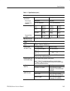
C
hann
e
l
-
to
-
chann
e
l
crosstalk, typical
Measured on one channel, with test signal applied to another channel,
and with the same scale and coupling settings on each channel
Frequency
range
TDS3012
TDS3014
TDS3032
TDS3034
TDS3052
TDS3054
≤ 100 MHz ≥ 100:1 ≥ 100:1 ≥ 100:1
≤ 300 MHz — ≥ 50:1 ≥ 50:1
≤ 500 MHz — — ≥ 30:1
Differential delay,
typical
100 ps between any two channels with the same scale and coupling
settings