


Operating Information
TDS3000 Series Service Manual
2–15
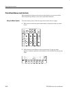
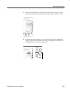
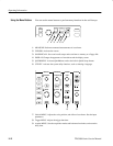
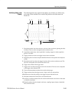
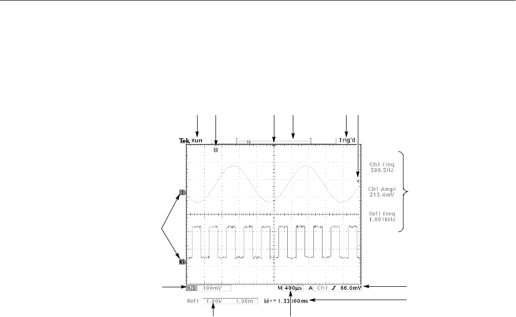
The following items may appear in the display; not all items are visible at any
given time. Some readouts move outside the graticule area when menus are
turned off.
1
8
7
11
2 3 4 5
9
10
13
12
6
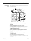
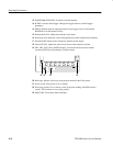
1. Waveform baseline icons show the zero-volt level of the waveforms (ignoring the effect
of offset). The icon colors correspond to the waveform colors.
2. Acquisition readout shows when acquisition is running, stopped, or when acquisition
preview is in effect.
3. Trigger position icon shows the trigger location in the waveforms.
4. Expansion point icon shows the point that the horizontal scale expands and compresses
around.
5. Waveform record icon shows the trigger location relative to the waveform record. The
line color corresponds to the selected waveform color.
6. Trigger status readout show trigger status.
7. Trigger level icon shows the trigger level on the waveform. The icon color corresponds
to the trigger source channel color.
8. Cursor and measurement readouts show results and messages.
9. Trigger readouts show the trigger sources, slopes, and levels, and position.
10. Readout shows the delay setting or the trigger location within the record.
11. Horizontal readout shows the main or zoom time/division.
12. Auxiliary waveform readouts show the vertical and horizontal scale factors of the math
or reference waveforms.
13. Channel readouts show the channel scale factor, coupling, input resistance, bandwidth
limit, and invert status.
Identifying Items in the
Display