


Maintenance
6–26
TDS3000 Series Service Manual
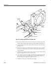
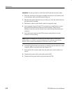
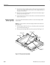
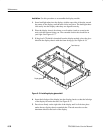
7. Insert the front chassis assembly into the oscilloscope. Insert the right end of
the front chassis slightly ahead of the left end to clear a slight interference at
the right end of the chassis.
8. Route the front-panel cable through the notch located on the bottom edge of
the front chassis. See Figure 6–14.
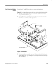
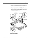
9. Use the Torx T-10 screwdriver to insert the two screws that secure the front
chassis to the front case.
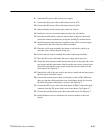
You will need a
1
8
inch flat-bladed screwdriver to remove the display module
inverter board.
Removal. Use this procedure to remove the display module inverter board and
back light tubes.
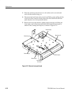
1. Place the display module face down on a soft surface (such as an anti-static
mat), with the bottom facing you.
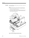
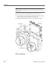
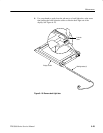
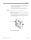
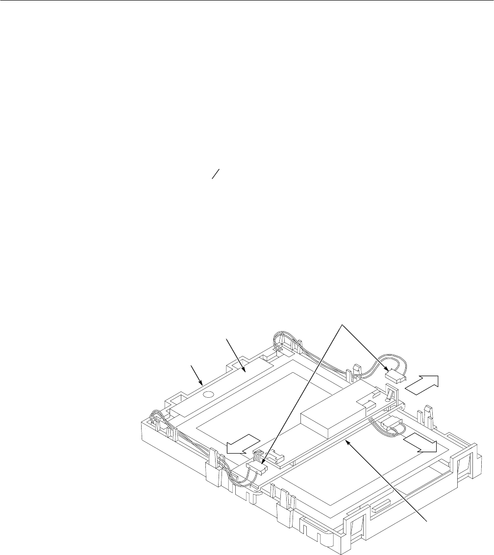
2. Disconnect the back light cables from the inverter board. See Figure 6–15.
Back light cables
Display module
Display chassis
Inverter board
assembly
Figure 6–15: Disconnect back light cables
Display Inverter Board
and Back light Tubes