


SECTION 4.2
OPERATIONAL ANALYSIS
PART 4
DC CONTROL
Page 4.2-11
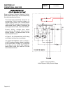
UTILITY
VOLTAGE
RESTORED
/
RE-
TRANSFER
TO
UTILITY
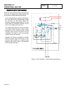
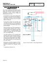
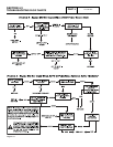
The "Load" is powered by the "Standby" power
supply. The circuit board continues to seek an
acceptable "Utility" source voltage. On
restoration of "Utility" source voltage, the
following events will occur:
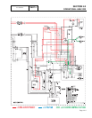
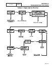
On restoration of utility source voltage above
80 percent of the nominal rated voltage, a
"retransfer time delay" on the circuit board
starts timing. The timer will run for about
fifteen (15) seconds.
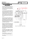
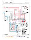
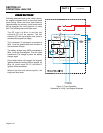
At the end of fifteen (15) seconds, the
"retransfer time delay" will stop timing and
circuit board action will open the Wire 23
circuit to ground. The transfer relay (TR) will
then de-energize.
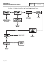
When the transfer relay (TR) de-energizes, its
normally-closed contacts close. "Utility"
source voltage is then delivered to the utility
closing coil (C1), via Wires N1A/N2A, the
closed TR contacts, Wire 126, limit switch
XA1, and a bridge rectifier.
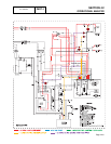
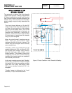
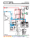
The utility closing coil (C1) energizes and
moves the main current carrying contacts to
their "Neutral" position. The main contacts
move to an over center position past "Neutral"
and spring force closes them to their "Utility"
side. "Load" terminals are now powered by
the "Utility" source.
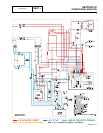
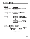
Movement of the main contacts to ’Utility"
actuates limit switches XA1/XB1. XA1 opens
and XB1 actuates to its "Standby" source
side.
The generator continues to run.
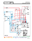
Figure 6. Circuit Condition - Utility Voltage Restored